Catalog PM 21 2013 - Siemens Industry, Inc.
Catalog PM 21 2013 - Siemens Industry, Inc.
Catalog PM 21 2013 - Siemens Industry, Inc.

You also want an ePaper? Increase the reach of your titles
YUMPU automatically turns print PDFs into web optimized ePapers that Google loves.
© <strong>Siemens</strong> AG <strong>2013</strong><br />
SINAMICS S120 drive system<br />
Control Units<br />
CU320-2 Control Unit<br />
■ Overview<br />
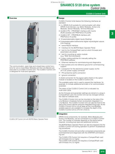
The communication, open-loop and closed-loop control functions<br />
for one or more Motor Modules and the Line Module are<br />
executed in a CU320-2 Control Unit. The CU320-2 Control Unit<br />
is designed for multi-axis operation.<br />
CU320-2 DP Control Unit with BOP20 Basic Operator Panel<br />
■ Design<br />
CU320-2 Control Units feature the following interfaces as<br />
standard:<br />
• 4 × DRIVE-CLiQ sockets for communication with other<br />
DRIVE-CLiQ devices, e.g. Motor Modules, Active Line<br />
Modules, Sensor Modules, Terminal Modules<br />
• CU320-2 PN: 1 PROFINET interface with 2 ports<br />
(RJ45 sockets) with PROFIdrive V4 profile<br />
• CU320-2 DP: 1 PROFIBUS interface with<br />
PROFIdrive V4 profile<br />
• 12 parameterizable digital inputs (floating)<br />
• 8 parameterizable bidirectional digital inputs/digital outputs<br />
(non-floating)<br />
• 1 serial RS232 interface<br />
• 1 interface for the BOP20 Basic Operator Panel<br />
• 1 slot for the CompactFlash card on which firmware and<br />
parameters are stored<br />
• 1 slot for mounting an option module<br />
(e.g. TB30 Terminal Board)<br />
• 2 rotary coding switches for manually setting the<br />
PROFIBUS address<br />
• 1 Ethernet interface for commissioning and diagnostics<br />
• 3 test sockets and one reference ground for commissioning<br />
support<br />
• 1 connection for the electronics power supply via the<br />
24 V DC power supply connector<br />
• 1 PE (protective earth) connection<br />
• 1 ground connection<br />
A shield connection for the signal cable shield on the option<br />
module is located on the CU320-2 Control Unit.<br />
The available option slot is used to expand the interfaces, for<br />
example, to include additional terminals or for communication<br />
purposes.<br />
The status of the CU320-2 Control Unit is indicated via<br />
multi-color LEDs.<br />
As the firmware and parameter settings are stored on a plug-in<br />
CompactFlash card, the Control Unit can be changed without<br />
the need for software tools.<br />
The CU320-2 Control Unit can be mounted on the side of the<br />
Line Module in booksize format via brackets integrated in a<br />
Line Module. The CU320-2 Control Unit can also be fixed to the<br />
wall of the control cabinet using the integrated fixing lugs. As the<br />
CU320-2 Control Unit is not as deep as the Line Modules,<br />
suitable spacers are available to increase the depth of the<br />
CU320-2 Control Unit to 270 mm (10.6 in).<br />
■ Integration<br />
DRIVE-CLiQ components, for example, Motor Modules and<br />
Active Line Modules, can be connected to a CU320-2 Control<br />
Unit. The number of modules depends on the performance<br />
required, including duty type and additional functions.<br />
The BOP20 Basic Operator Panel can also be snapped onto the<br />
CU320-2 Control Unit during operation to perform troubleshooting<br />
procedures.<br />
The CU320-2 Control Unit and other connected components are<br />
commissioned and diagnosed with the STARTER commissioning<br />
tool.<br />
The CU320-2 PN Control Unit requires a CompactFlash card<br />
with firmware V4.4 or higher.<br />
The CU320-2 DP Control Unit requires a CompactFlash card<br />
with firmware V4.3 or higher.<br />
3<br />
<strong>Siemens</strong> <strong>PM</strong> <strong>21</strong> · <strong>2013</strong><br />
3/19