Catalog PM 21 2013 - Siemens Industry, Inc.
Catalog PM 21 2013 - Siemens Industry, Inc.
Catalog PM 21 2013 - Siemens Industry, Inc.

Create successful ePaper yourself
Turn your PDF publications into a flip-book with our unique Google optimized e-Paper software.
SINAMICS S120 drive system<br />
DC link components<br />
Braking Modules in chassis format<br />
© <strong>Siemens</strong> AG <strong>2013</strong><br />
3<br />
■ Overview<br />
the DC link power is converted into heat loss in an external<br />
braking resistor. Braking Modules function autonomously. A<br />
number of Braking Modules can be operated in parallel. In this<br />
case, each Braking Module must have its own braking resistor.<br />
Braking Modules are designed to be built into Motor Modules,<br />
Line Modules or Power Modules in chassis format and are<br />
cooled by the fans on these modules. The supply voltage for the<br />
electronics is taken from the DC link. The Braking Modules are<br />
connected to the DC link by means of the busbar sets included<br />
in the scope of supply or flexible cables and, in the case of the<br />
Basic Line Module of frame size GB, by means of a separate<br />
molded cable set (see Accessories).<br />
The activation threshold of the Braking Module can be adjusted<br />
by means of a DIP switch. The braking power values specified<br />
in the technical data apply to the upper activation threshold.<br />
A Braking Module and the matching external braking resistor are<br />
required to bring drives to a controlled standstill in the event of a<br />
power failure (e.g. emergency retraction or EMERGENCY STOP)<br />
or limit the DC link voltage for brief periods of generator operation,<br />
e.g. when the regenerative feedback capability of the Line<br />
Module is deactivated. The Braking Module includes the power<br />
electronics and the associated control circuit. During operation,<br />
■ Design<br />
The Braking Modules in chassis format feature the following<br />
connections and interfaces as standard:<br />
• 1 DC link connection<br />
• 1 braking resistor connection<br />
• 1 digital input (inhibit Braking Module/acknowledge fault)<br />
• 1 digital output (Braking Module inhibited)<br />
• 1 DIP switch for adjusting the activation threshold<br />
■ Integration<br />
Braking Modules in chassis format are designed for mounting in<br />
air-cooled units in chassis format. The fan of the Line Module,<br />
Motor Module or Power Module in which the Braking Module is<br />
mounted also cools the Braking Module. Braking Modules<br />
cannot operate autonomously because they are not equipped<br />
with cooling fans.<br />
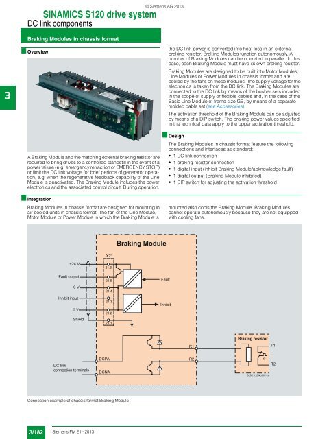
Braking Module<br />
X<strong>21</strong><br />
+24 V<br />
Fault output<br />
0 V<br />
Inhibit input<br />
0 V<br />
Shield<br />
<strong>21</strong>.6<br />
<strong>21</strong>.5<br />
<strong>21</strong>.4<br />
<strong>21</strong>.3<br />
<strong>21</strong>.2<br />
<strong>21</strong>.1<br />
Fault<br />
Inhibit<br />
R1<br />
Braking resistor<br />
T1<br />
DC link<br />
connection terminals<br />
DCPA<br />
DCNA<br />
R2<br />
G_D<strong>21</strong>1_EN_00012a<br />
T2<br />
Connection example of chassis format Braking Module<br />
3/182 <strong>Siemens</strong> <strong>PM</strong> <strong>21</strong> · <strong>2013</strong>