C. EES Point T i p i ṁ i qu i h i w i ∆˙ [ ] [ ] H i [C ] [kPa] kg /s [-] k J/kg [-] [kW ] 35 21,81 2000 4,807 36 23,32 2000 4,807 37 26,71 2000 4,807 113,7 38 30 2000 0,06077 127,5 39 21,81 2000 4,807 93,29 40 41 138 2000 1,852 42 133 2000 1,852 560,4 43 138 2000 1,852 581,7 45 30 100 7,426 57,67 46 30,32 100,2 7,426 47 23,71 100 7,486 71,7 48 11 2000 2,808 49 6 2000 2,808 50 67 4,708 0,01101 100 2625 0 51 31,81 4,708 0,02474 0,5051 1358 0 52 31,81 4,708 0,02474 0 133,3 0 53 3,31 0,7749 0,02474 0,04788 133,3 0 54 3,31 0,7749 0,02474 1 2507 0 55 28,52 0,7749 0,3205 0 64,18 0,5282 56 28,52 4,708 0,3205 -100 64,19 0,5282 57 57,29 4,708 0,3205 -100 123,3 0,5282 58 57,29 4,708 0,1987 -100 123,3 0,5282 59 67 4,708 0,1876 0 152,5 0,5592 60 65,39 4,708 0,2957 -100 153,8 0,5724 61 33,52 4,708 0,2957 -100 89,74 0,5724 62 33,03 0,7749 0,2957 -100 89,74 0,5724 70 133 51,4 0,01374 100 2746 0 71 133 51,4 0,01374 100 2746 0 72 82 51,4 0,01374 0 343,3 0 73 31,81 4,708 0,01374 0,08661 343,3 0 75 57,29 4,708 0,1218 -100 123,3 0,5282 76 57,32 51,4 0,1218 -100 123,4 0,5282 77 117 51,4 0,1218 -100 249,6 0,5282 78 117 51,4 0,1218 -100 249,6 0,5282 79 133 51,4 0,1081 0 298,4 0,5954 80 133 51,4 0,1081 0 298,4 0,5954 81 62,32 51,4 0,1081 -100 156,1 0,5954 82 61,44 4,708 0,1081 -100 156,1 0,5954 256
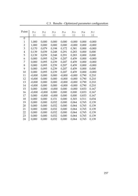
C.3. Results - Optimized parameter configuration Point y i ;1 y i ;2 y i ;3 y i ;4 y i ;5 y i ;6 y i ;7 [-] [-] [-] [-] [-] [-] [-] 0 1 1,000 0,000 0,000 0,000 -0,000 0,000 -0,000 2 1,000 0,000 0,000 0,000 -0,000 0,000 -0,000 3 0,170 0,079 0,198 0,172 0,381 0,000 -0,000 4 0,139 0,039 0,248 0,291 0,283 0,000 0,000 5 0,139 0,039 0,248 0,291 0,283 0,000 0,000 6 0,000 0,095 0,239 0,207 0,459 0,000 -0,000 7 0,000 0,095 0,239 0,207 0,459 0,000 -0,000 8 0,000 0,095 0,239 0,207 0,459 0,000 -0,000 9 0,000 0,095 0,239 0,207 0,459 0,000 0,000 10 0,000 0,095 0,239 0,207 0,459 0,000 -0,000 11 -0,000 0,000 0,000 -0,000 -0,000 0,790 0,210 12 -0,000 0,000 0,000 -0,000 -0,000 0,790 0,210 13 -0,000 0,000 0,000 -0,000 -0,000 0,790 0,210 14 -0,000 0,000 0,000 -0,000 -0,000 0,790 0,210 15 0,000 0,000 -0,000 0,000 -0,000 0,833 0,167 16 -0,000 -0,000 0,000 0,000 0,000 0,833 0,167 17 0,000 -0,000 -0,000 0,000 0,000 0,833 0,167 18 0,000 0,000 0,151 0,000 0,303 0,511 0,034 19 0,000 0,000 0,032 0,000 0,064 0,765 0,139 20 0,000 0,000 0,032 0,000 0,064 0,765 0,139 21 0,000 0,000 0,032 0,000 0,064 0,765 0,139 22 0,000 0,000 0,032 0,000 0,064 0,765 0,139 23 0,000 0,000 0,032 0,000 0,064 0,765 0,139 24 0,000 0,000 0,032 0,000 0,064 0,765 0,139 257
- Page 1:
INTEGRATION OF SOLID OXIDE FUEL CEL
- Page 5:
Abstract It is investigated whether
- Page 9:
Preface This report is documentatio
- Page 12 and 13:
CONTENTS Preface . . . . . . . . .
- Page 14 and 15:
CONTENTS 4.2.3 SOFC stack . . . . .
- Page 16 and 17:
CONTENTS A.4 DG appendix . . . . .
- Page 18 and 19:
LIST OF FIGURES 4.3 Diagram of sing
- Page 21 and 22:
NOMENCLATURE Acronyms Acronym ABS A
- Page 23 and 24:
Greek (and other) Symbols Greek (an
- Page 25:
Subscripts Subscripts Subscript 2P
- Page 28 and 29:
1. INTRODUCTION Chapter 4, System d
- Page 30 and 31:
1. INTRODUCTION the electricity and
- Page 32 and 33:
1. INTRODUCTION 1.4 SOFC The fuel c
- Page 34 and 35:
1. INTRODUCTION 1.5 Heat driven coo
- Page 36 and 37:
1. INTRODUCTION Cycle description.
- Page 38 and 39:
1. INTRODUCTION Ammonia-water The C
- Page 40 and 41:
1. INTRODUCTION 1.5.3 Platen Munter
- Page 42 and 43:
1. INTRODUCTION Open loop In an ope
- Page 44 and 45:
1. INTRODUCTION 1.7 Problem stateme
- Page 46 and 47:
2. MARKET INVESTIGATION appendix A.
- Page 48 and 49:
2. MARKET INVESTIGATION 2.2.2 Ship
- Page 50 and 51:
2. MARKET INVESTIGATION Pay Back Ti
- Page 52 and 53:
2. MARKET INVESTIGATION 2.3.2 Micro
- Page 54 and 55:
2. MARKET INVESTIGATION Sensitivity
- Page 56 and 57:
2. MARKET INVESTIGATION • ECH pri
- Page 58 and 59:
2. MARKET INVESTIGATION 2.4.3 Resul
- Page 60 and 61:
2. MARKET INVESTIGATION 16000 14000
- Page 62 and 63:
2. MARKET INVESTIGATION Annuity pri
- Page 64 and 65:
2. MARKET INVESTIGATION 2.4.4 Concl
- Page 67 and 68:
C H A P T E R 3 COMPONENT DESCRIPTI
- Page 69 and 70:
3.1. Introduction The seven stream
- Page 71 and 72:
3.2. Absorber - ABSO 3.2 Absorber -
- Page 73 and 74:
3.2. Absorber - ABSO implicitly thr
- Page 75 and 76:
3.4. Burner - BURN 3.4 Burner - BUR
- Page 77 and 78:
3.5. Condenser - COND T [° C ] ΔT
- Page 79 and 80:
3.6. Desorber - DES 3.6 Desorber -
- Page 81 and 82:
3.7. Evaporator - EVAP 3.7 Evaporat
- Page 83 and 84:
3.8. Heat Exchanger - HEX 3.8 Heat
- Page 85 and 86:
3.8. Heat Exchanger - HEX The press
- Page 87 and 88:
3.10. Pre Reformer - PR 3.10 Pre Re
- Page 89 and 90:
3.11. Pump - PUMP 3.11 Pump - PUMP
- Page 91 and 92:
3.12. Solid Oxide Fuel Cell - SOFC
- Page 93 and 94:
3.12. Solid Oxide Fuel Cell - SOFC
- Page 95 and 96:
3.12. Solid Oxide Fuel Cell - SOFC
- Page 97 and 98:
3.14 Cooling Tower - TOWER 3.14. Co
- Page 99 and 100:
3.14. Cooling Tower - TOWER tower d
- Page 101 and 102:
3.14. Cooling Tower - TOWER The air
- Page 103:
3.15. Expansion valve - VA/VB possi
- Page 106 and 107:
4. SYSTEM DESCRIPTION 8 SPG 10 20 1
- Page 108 and 109:
4. SYSTEM DESCRIPTION Pre reformer
- Page 110 and 111:
4. SYSTEM DESCRIPTION which increas
- Page 112 and 113:
4. SYSTEM DESCRIPTION 4.3 Absorptio
- Page 114 and 115:
4. SYSTEM DESCRIPTION 4.3.3 Pumping
- Page 116 and 117:
4. SYSTEM DESCRIPTION The temperatu
- Page 118 and 119:
4. SYSTEM DESCRIPTION 4.5 Absorptio
- Page 120 and 121:
4. SYSTEM DESCRIPTION 4.6 Cooling T
- Page 122 and 123:
4. SYSTEM DESCRIPTION (below 100
- Page 124 and 125:
4. SYSTEM DESCRIPTION as: Ẇ AC =
- Page 126 and 127:
4. SYSTEM DESCRIPTION 4.8 Verificat
- Page 128 and 129:
4. SYSTEM DESCRIPTION SOFC net effi
- Page 131 and 132:
C H A P T E R 5 SIMULATION AND RESU
- Page 133 and 134:
5.1. Basic absorption cooling Figur
- Page 135 and 136:
5.1. Basic absorption cooling geous
- Page 137 and 138:
5.1.3 Changing evaporator temperatu
- Page 139 and 140:
5.1. Basic absorption cooling as de
- Page 141 and 142:
5.2. System configurations Red repr
- Page 143 and 144:
5.2. System configurations Dual Hea
- Page 145 and 146:
5.2. System configurations in a hot
- Page 147 and 148:
5.3. Partial optimization of standa
- Page 149 and 150:
5.3. Partial optimization of standa
- Page 151 and 152:
5.3. Partial optimization of standa
- Page 153 and 154:
5.3. Partial optimization of standa
- Page 155 and 156:
Anode recycling (α SPG1 ) 5.3. Par
- Page 157 and 158:
5.3. Partial optimization of standa
- Page 159 and 160:
5.3. Partial optimization of standa
- Page 161 and 162:
5.3. Partial optimization of standa
- Page 163 and 164:
5.3. Partial optimization of standa
- Page 165 and 166:
5.3. Partial optimization of standa
- Page 167 and 168:
5.3. Partial optimization of standa
- Page 169 and 170:
5.4. Sensitivity Analysis ηsys,el,
- Page 171 and 172:
5.4. Sensitivity Analysis the press
- Page 173 and 174:
5.4. Sensitivity Analysis 1. The x-
- Page 175 and 176:
5.5 Total optimization of system 5.
- Page 177 and 178:
5.5. Total optimization of system i
- Page 179 and 180:
5.5. Total optimization of system e
- Page 181 and 182:
C H A P T E R 6 CASES AND ECONOMICS
- Page 183 and 184:
6.2. High humidity climate BBC Home
- Page 185 and 186:
6.2. High humidity climate Figure 6
- Page 187 and 188:
6.3. Low humidity climate Figure 6.
- Page 189 and 190:
6.4. Economics 6.4 Economics When t
- Page 191 and 192:
C H A P T E R 7 DISCUSSION In this
- Page 193 and 194:
7.1.1 Accuracy and sensitivity 7.1.
- Page 195 and 196:
7.2. Economical considerations Furt
- Page 197 and 198:
7.2.3 Distributed Generation (DG) D
- Page 199 and 200:
7.2. Economical considerations to 6
- Page 201 and 202:
7.2. Economical considerations As m
- Page 203 and 204:
C H A P T E R 8 CONCLUSION System c
- Page 205 and 206:
For the APU segment a SOFC-ABS syst
- Page 207 and 208:
C H A P T E R 9 FURTHER WORK Some i
- Page 209 and 210:
BIBLIOGRAPHY [1] Acfshop.dk: http:/
- Page 211 and 212:
Bibliography [24] Nordea invest: ht
- Page 213:
Appendices 187
- Page 216 and 217:
A. MARKET INVESTIGATION A.1 Market
- Page 218 and 219:
A. MARKET INVESTIGATION No cost for
- Page 220 and 221:
Absorpton unit (free waste heat) Pr
- Page 222 and 223:
A. MARKET INVESTIGATION A.3 CHP app
- Page 224 and 225:
Absorption Refrigerator RGE 400 fro
- Page 226 and 227:
Sensitivity analysis The effect on
- Page 228 and 229:
A. MARKET INVESTIGATION A.4 DG appe
- Page 230 and 231:
From the "CHP in the Hotel and Casi
- Page 232 and 233: Hotel with 230 rooms and 18000 m^2
- Page 234 and 235: SOFC + Water Heating (no ABS), Cool
- Page 236 and 237: 16000 Pay Back Time: Entire System
- Page 238 and 239: SOFC + Water Heating (no ABS), Cool
- Page 240 and 241: Hot climate SOFC + ABS + HW vs pure
- Page 242 and 243: Assumptions SOFC price = 2650kr/kW
- Page 244 and 245: Hot climate Increase (Delta NPV_10)
- Page 246 and 247: Prices of absorption cooling units
- Page 248 and 249: 1'000'000 900'000 800'000 143'600 7
- Page 250 and 251: A. MARKET INVESTIGATION A.6 Gas and
- Page 252 and 253: Retail electricity prices Exchange
- Page 254 and 255: B. DIAGRAMS AND PLOTS B.1 GAX diagr
- Page 256 and 257: B. DIAGRAMS AND PLOTS B.3 Closed ad
- Page 258 and 259: B. DIAGRAMS AND PLOTS B.4.2 p-T dia
- Page 260 and 261: C. EES Efficiencies SOFC η inver t
- Page 262 and 263: C. EES ∆ p;GGHE X 1;c = −1 [kPa
- Page 264 and 265: C. EES ˙Q loss;Bur n = 0 [kW ] ˙Q
- Page 266 and 267: C. EES SOFC ∆ T ;SOFC ;av = 30 [C
- Page 268 and 269: C. EES C.2 Results - Standard param
- Page 270 and 271: C. EES 244 DES2 h;o = 42 DES2 i = 7
- Page 272 and 273: C. EES SOFC ano;i = 5 SOFC ano;o =
- Page 274 and 275: C. EES Point T i p i ṁ i qu i h i
- Page 276 and 277: C. EES C.3 Results - Optimized para
- Page 278 and 279: C. EES ∆ T ;min;W GHE X 3;w;i = 1
- Page 280 and 281: C. EES ˙Q tr ans;W GHE X 3 = 2,752
- Page 284 and 285: C. EES C.4 Results - Uncertainty pr
- Page 286 and 287: C. EES ∆T ;min;W GHE X 3;w;i = 15
- Page 288 and 289: C. EES ∆p;TOW ER1;air ;dr y = 0,1
- Page 290 and 291: C. EES ∆p;GGHE X 1;c = −1 ±
- Page 292 and 293: C. EES C.4.4 ∆p for absorption su
- Page 294 and 295: C. EES C.4.5 ˙Qloss for absorption
- Page 297 and 298: A P P E N D I X D OTHER D.1 Explana
- Page 299 and 300: D.3. Water consumption Hence it is
- Page 301 and 302: A P P E N D I X E OPTIMIZATION GRAP
- Page 303 and 304: E.1. Simulations and Results E.1.2
- Page 305 and 306: E.1. Simulations and Results Figure
- Page 307 and 308: E.1. Simulations and Results Figure
- Page 309: E.2. Cases E.2 Cases E.2.1 Extreme
- Page 312 and 313: SEG Scandinavian Energy Group Aps.
- Page 314 and 315: SEG Scandinavian Energy Group Aps.
- Page 316 and 317: SEG Scandinavian Energy Group Aps.
- Page 318 and 319: SEG Scandinavian Energy Group Aps.
- Page 320 and 321: 8 SPG 1 10 1-α GGHEX1 9 α 7 GGHEX
- Page 322: 1 8 GGHEX1 CH4, in Air, in 21 2 11