Summary Report for Conduct of Kozloduy NPP Stress Tests
Summary Report for Conduct of Kozloduy NPP Stress Tests
Summary Report for Conduct of Kozloduy NPP Stress Tests

You also want an ePaper? Increase the reach of your titles
YUMPU automatically turns print PDFs into web optimized ePapers that Google loves.
“<strong>Kozloduy</strong> <strong>NPP</strong>” PLC<br />
SUMMARY REPORT<br />
<strong>for</strong> <strong>Conduct</strong> <strong>of</strong> <strong>Kozloduy</strong> <strong>NPP</strong><br />
<strong>Stress</strong> <strong>Tests</strong><br />
prevented. These DGs can be used also <strong>for</strong> removal <strong>of</strong> reactor decay heat as well as in case <strong>of</strong><br />
failure to the three emergency DGs. Additional DGs are in hot standby mode.<br />
Additional DG is located in the container <strong>of</strong> plat<strong>for</strong>m <strong>of</strong> 1m above the site and according<br />
[7]and [8] refer to class 4 by OPB-88/97 and respective seismic category 2.<br />
Total fuel and oil reserve <strong>of</strong> additional DGs ensure uninterrupted operation <strong>of</strong> each <strong>of</strong> them<br />
<strong>for</strong> more than 4 days<br />
5.1.1.2.2 Capacity <strong>of</strong> the batteries, operational time period and capabilities to recharge the<br />
batteries<br />
No possibility is envisioned to recharge the accumulator batteries <strong>of</strong> the safety system from<br />
additional or mobile DG. Their charging is provided from emergency DG <strong>of</strong> the related safety train<br />
<strong>of</strong> the SS. Common-plant accumulator battery and that <strong>of</strong> the computer-based in<strong>for</strong>mational system<br />
can be charged from additional diesel generator. Full description <strong>of</strong> accumulator battery description<br />
is provided in par. 1.3.2.6.1. „Accumulator batteries“.<br />
5.1.1.2.3 Time to reaching severe accident in the specified conditions. Threshold values in plant<br />
behaviour<br />
The following conditions <strong>of</strong> the units were assessed:<br />
· Power operations;<br />
· Cold condition (N=18 MW, 20 hours after shutdown), pressurized primary circuit<br />
and drained SG;<br />
· Cold condition (N=18 MW, 20 hours after shutdown), pressurized primary circuit<br />
and non-drained SG;<br />
· Cold condition (N=16.2 MW, 28 hours after shutdown), depressurized primary<br />
circuit;<br />
· Outage cooldown <strong>of</strong> the primary circuit (N=12 MW, 72 hours after shutdown and<br />
N=6 MW, about 18 days after shutdown).<br />
Operator actions aimed at prolongation <strong>of</strong> the time period be<strong>for</strong>e fuel damage occurs are<br />
specified <strong>for</strong> each <strong>of</strong> the modes considered in the analyses<br />
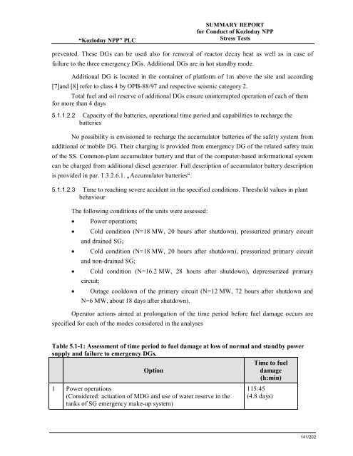
Table 5.1-1: Assessment <strong>of</strong> time period to fuel damage at loss <strong>of</strong> normal and standby power<br />
supply and failure to emergency DGs.<br />
Time to fuel<br />
Option<br />
damage<br />
(h:min)<br />
1 Power operations<br />
(Considered: actuation <strong>of</strong> MDG and use <strong>of</strong> water reserve in the<br />
tanks <strong>of</strong> SG emergency make-up system)<br />
115:45<br />
(4.8 days)<br />
141/202