Attention! Your ePaper is waiting for publication!
By publishing your document, the content will be optimally indexed by Google via AI and sorted into the right category for over 500 million ePaper readers on YUMPU.
This will ensure high visibility and many readers!

Your ePaper is now published and live on YUMPU!
You can find your publication here:
Share your interactive ePaper on all platforms and on your website with our embed function

power distribution - Siemens
power distribution - Siemens
power distribution - Siemens
- No tags were found...
You also want an ePaper? Increase the reach of your titles
YUMPU automatically turns print PDFs into web optimized ePapers that Google loves.
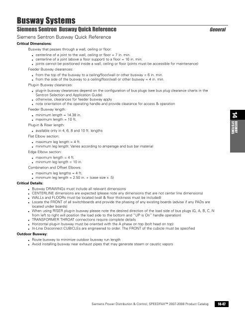
Busway Systems<strong>Siemens</strong> Sentron Busway Quick Reference<strong>Siemens</strong> Sentron Busway Quick ReferenceCritical Dimensions:Busway that passes through a wall, ceiling or floor:▪ centerline of a joint to the wall, ceiling or floor = 7 in. min.▪ centerline of a joint (above a floor support) to a floor = 16 in. min.▪ joints cannot be positioned inside a wall, ceiling or floor (joints must be accessible for maintenance)Feeder Busway clearances:▪ from the top of the busway to a ceiling/floor/wall or other busway = 6 in. min.▪ from the side of the busway to a ceiling/floor/wall or other busway = 4 in. min.Plug-in Busway clearances:▪ plug-in busway clearances depend on the configuration of bus plugs (see bus plug clearance charts in theSentron Selection and Application Guide)▪ otherwise, clearances for feeder busway apply▪ note orientation of the operating handle and provide clearance for access & operationFeeder Busway length:▪ minimum length = 14.38 in.▪ maximum length = 10 ft.Plug-in & Riser length:▪ available only in 4, 6, 8 and 10 ft. lengthsFlat Elbow section:▪ maximum leg length = 4 ft.▪ minimum leg length: Varies according to amperage and bus bar materialEdge Elbow section:▪ maximum length = 4 ft.▪ minimum leg length = 10 in.Combination and Offset Elbows:▪ maximum leg lengths = 4 ft.▪ minimum leg length = 2.50 in. + (case size x .5)Critical Details:▪ Busway DRAWINGs must include all relevant dimensions▪ CENTERLINE dimensions are expected (please note any dimensions that are not center line dimensions)▪ WALLs and FLOORs must be located (wall & floor thickness must be included)▪ Locate the FRONT of all switchboards and provide the phasing of any existing boards (advise if any PADs arelocated under boards)▪ When using RISER plug-in busway please note the desired direction of the load side of bus plugs (G, A, B, C, Nfrom left to right will position the load side to the bottom and “UP is On” handle operation)▪ TRANSFORMER THROAT connections require complete details▪ Horizontal plug-in busway must be oriented with the A phase on top (bolt head on top)▪ In-Line Disconnect CUBICLEs are engineered to order. The FRONT of the cubicle must be specifiedOutdoor Busway:▪ Route busway to minimize outdoor busway run length▪ Avoid installing busway near exhaust pipes that may generate steam or caustic vaporsGeneral14 BUSWAYSYSTEMS<strong>Siemens</strong> Power Distribution & Control, SPEEDFAX 2007-2008 Product Catalog 14-47
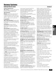
14BUSWAYSYSTEMSBusway SystemsInstallation and Application InformationInstallationIn preparation for installation of yourbusway systems, it is important tofamiliarize yourself with the followinginstallation publications:▪ General Instructions For Handling,Installation, Operation andMaintenance of Busway Rated 600volts or less (NEMA StandardsPublication BU1)▪ Storage, Installation andMaintainance Instructions for SentronBusway (31-9918-01)These publications should be readthrough thoroughly and used asreference during installation to ensureproper installation procedures. AllBusway Order Entry ChecklistNote: Submit one checklist for each busway run.Date Submitted: ____________Purchase Order #: _______________________Project Name: _____________________________Submitted By: _____________________________Sales Engineer: _________________________________ Released _____ Hold for ReleaseRun Designation: ___________________________Busway Catalog #: __________________________Service: _____ Phase _____ Wire _____ Volts _____ AmpsConductor: _____ Cu _____ Al _____ “M” Rated _____ “L”RatedNeutral: _____ None _____ 100% _____ 200%Ground: _____ Case _____ Internal _____ IsolatedIP Rating _____ IP40 (Indoor)_____ IP55 (Splash Proof)_____ NEMA 3R (Outdoor)Shipping Instructions:_____ Ship complete _____ Ship partialSpecial Shipping Requirements:___________________________Ship not before date: ____________Drawing Requirements:_____ Approval drawings _____ # copies:_____ Record drawings _____ # copies:A) Engineering InformationCheck applicable information and be sure it is shown onaccompanying drawing.equipment should be inspected upondelivery. If the busway is not installedimmediately, it should be stored in aclean, dry location. Factory suppliedrecord drawings as well as installationtools should be accessible in preparationfor installation.UL 1479 Fire Rated InstallationsSentron Busway has been tested inaccordance with UL 1479 and offers acertified two hour fire rating for gypsumwallboard construction and a three hourfire rating for concrete slab or blockpenetrations. These ratings wereachieved using standard buswayinstalled with SpecSeal ® sealant fromSpecified Technologies Inc. TheSpecSeal ® fire stop system providessuperior11. _____ Riser Busa) _____ Load side of bus plug (top or bottom)b) _____ Required distance from floor to top ofpanel/plugsc) _____ Meter Bank (center line of tap stack)d) _____ Barriers and/or floor supports12. _____ Transformer Connectionsa) _____Standard XFMR Service Heads_____ 1-three phase_____ 3-single phaseb) Special drawing required_____ Dimensions between phases_____ LV spade detail including drilling andthickness_____ Dimension of the LV spade from tank wall_____ Throat opening and hole pattern (if any)13. _____ Utility Vault Connection Utility Type: __________ Drawing Attached14. End Cable Tap Box_____ Horizontal_____ Vertical_____ Standard Lugs_____ Special Lug RequirementsNo. _____ Size _____ per phase & neutralNo. _____ Size _____ per ground15. _____ Busway Mounting position in reference to floor:Selectionperformance at the industry’s lowestinstalled cost. Sentron is the firstbusway system to achieve a fire ratingfor gypsum wallboard construction.MeasuringCritical to the success of any buswayinstallation is the layout and the accuratemeasuring of the busway. First andforemost:Select a route for your busway that willrequire the fewest fittings and themaxumum number of 10' (3.05m) sections.It is important that the busway system bedesigned to meet the requirements of theNational Electric Code for Busway. Thereare a number of techniques that may beused to ensure an accurate measurementbefore purchasing and installing thebusway. The following tools will berequired during layout and masuring:▪ 100' (30.48m) tape measure▪ Meauring Stick▪ Chalkline▪ Plumb Bob▪ Marker(A laser distance measuring device maybe used to speed the measuringprocess).1. _____ Drawing Attached (Required)2. _____ Estimate Sheets Attached (Required)3. _____ Dimensions from walls, column lines, etc.4. _____ Wall, floor, roof thickness and pitch5. _____ Floor Elevations_____ Floor to floor_____ Floor to ceiling6. _____ Wall Locations7. _____ Equipment Pads shown: Height _______8. ____ Existing busway to be extendeda) _____ Phasingb) _____ Nameplate Informatioc) _____ Match to competitor: Call the factory9. ____ Secial Switchboard Connection: Provide Details10. ____ Phase transpositions: Provide phasing on drawing.FlatwiseEdgewiseB) Specifications(Check or fill appropriate blanks)1. _____ Standard busway meets specifications2. _____ Exception to specificationsa) Short circuit withstand _____ Ampere Symmetricalb) Voltage Drop Requirement _____c) Temperature-rise requirement _____d) Current density requirement _____e) Special Paint: Provide paint chip _____f) Other: ____________________________Exception to electrical specifications: Call the factory.Other Notes: _________________________________________________________________________________________________________________________________Minimal ClearancesMinimum clearances for installing feederbusway are shown. Additional clearancemay be required for plug-in deviceslarger than 100A fusible and 250A circuitbreaker.14-46<strong>Siemens</strong> Power Distribution & Control, SPEEDFAX 2007-2008 Product Catalog
Busway Systems<strong>Siemens</strong> Sentron Busway Quick Reference<strong>Siemens</strong> Sentron Busway Quick ReferenceCritical Dimensions:Busway that passes through a wall, ceiling or floor:▪ centerline of a joint to the wall, ceiling or floor = 7 in. min.▪ centerline of a joint (above a floor support) to a floor = 16 in. min.▪ joints cannot be positioned inside a wall, ceiling or floor (joints must be accessible for maintenance)Feeder Busway clearances:▪ from the top of the busway to a ceiling/floor/wall or other busway = 6 in. min.▪ from the side of the busway to a ceiling/floor/wall or other busway = 4 in. min.Plug-in Busway clearances:▪ plug-in busway clearances depend on the configuration of bus plugs (see bus plug clearance charts in theSentron Selection and Application Guide)▪ otherwise, clearances for feeder busway apply▪ note orientation of the operating handle and provide clearance for access & operationFeeder Busway length:▪ minimum length = 14.38 in.▪ maximum length = 10 ft.Plug-in & Riser length:▪ available only in 4, 6, 8 and 10 ft. lengthsFlat Elbow section:▪ maximum leg length = 4 ft.▪ minimum leg length: Varies according to amperage and bus bar materialEdge Elbow section:▪ maximum length = 4 ft.▪ minimum leg length = 10 in.Combination and Offset Elbows:▪ maximum leg lengths = 4 ft.▪ minimum leg length = 2.50 in. + (case size x .5)Critical Details:▪ Busway DRAWINGs must include all relevant dimensions▪ CENTERLINE dimensions are expected (please note any dimensions that are not center line dimensions)▪ WALLs and FLOORs must be located (wall & floor thickness must be included)▪ Locate the FRONT of all switchboards and provide the phasing of any existing boards (advise if any PADs arelocated under boards)▪ When using RISER plug-in busway please note the desired direction of the load side of bus plugs (G, A, B, C, Nfrom left to right will position the load side to the bottom and “UP is On” handle operation)▪ TRANSFORMER THROAT connections require complete details▪ Horizontal plug-in busway must be oriented with the A phase on top (bolt head on top)▪ In-Line Disconnect CUBICLEs are engineered to order. The FRONT of the cubicle must be specifiedOutdoor Busway:▪ Route busway to minimize outdoor busway run length▪ Avoid installing busway near exhaust pipes that may generate steam or caustic vaporsGeneral14 BUSWAYSYSTEMS<strong>Siemens</strong> Power Distribution & Control, SPEEDFAX 2007-2008 Product Catalog 14-47
- Page 1 and 2:
SPEEDFAX TM 2007-2008 Product Catal
- Page 3 and 4:
Reliable Products From TheTechnolog
- Page 5 and 6:
1SPEEDFAX TM 2007-2008 Load Centers
- Page 7 and 8:
EQ ® and Ultimate Load CentersSeri
- Page 9 and 10:
Ultimate Load CentersProduct Offeri
- Page 11 and 12:
The Ultimate Load CentersSingle Pha
- Page 13 and 14:
EQ ® Load CentersSmall Circuit Loa
- Page 15 and 16:
EQ ® Load Centers3-Phase Main Brea
- Page 17 and 18:
Load CentersSpecial Application Loa
- Page 19 and 20:
AC Disconnects1-Phase, NEMA 3R Rate
- Page 21 and 22:
Ultimate Load CentersMain Breaker W
- Page 23 and 24:
EQ Load Centers3-Phase Load CenterW
- Page 25 and 26:
Ultimate Load CenterIndoor and Outd
- Page 27 and 28:
EQ ® Load CentersIndoor Enclosures
- Page 29 and 30:
Circuit BreakersDuplex, Triplex and
- Page 31 and 32:
Circuit BreakersSpecial Application
- Page 33 and 34:
Circuit BreakersMain and Branch Cir
- Page 35 and 36:
Circuit BreakersLug DataReferenceCi
- Page 37 and 38:
Surge ProtectionPoint-of-EntryTrans
- Page 39 and 40:
ElectricenterAccessories Circuit Br
- Page 41 and 42:
All-Sites Temporary Power Outlet Pa
- Page 43 and 44:
All-Sites Temporary Power Outlet Pa
- Page 45 and 46:
Temporary Power Outlet PanelsStanda
- Page 47 and 48:
Temporary Power Outlet PanelsDimens
- Page 49 and 50:
Temporary Power Outlet PanelsDimens
- Page 51 and 52:
2SPEEDFAX TM 2007-2008 Meter Center
- Page 53 and 54:
Meter CentersMeter Socket Bypass Ty
- Page 55 and 56:
Meter CentersSingle Position Meter
- Page 57 and 58:
Meter CentersSingle Position Meter
- Page 59 and 60:
Meter CentersEUSERC Meter Sockets
- Page 61 and 62:
Meter CentersKnockout DiagramsSelec
- Page 63 and 64:
Meter CentersKnockout DiagramsSelec
- Page 65 and 66:
Meter CentersKnockout DiagramsSelec
- Page 67 and 68:
Meter CentersKnockout DiagramsSelec
- Page 69 and 70:
Meter CentersSurface Mount Meter Ma
- Page 71 and 72:
Meter CentersSurface Mount Meter Lo
- Page 73 and 74:
Meter CentersNEWEUSERC Meter Load C
- Page 75 and 76:
Meter CentersMeter Load Centers Sin
- Page 77 and 78:
Meter CentersDimensions and Wiring
- Page 79 and 80:
EQPT GRDEQPT GRDNEUTRALNEUTRALEQPT
- Page 81 and 82:
Meter CentersDimensions and Wiring
- Page 83 and 84:
Meter CentersDimensions and Wiring
- Page 85 and 86:
Meter CentersDimensions and Wiring
- Page 87 and 88:
Meter CentersDimensions and Wiring
- Page 89 and 90:
Meter CentersModular Metering: Sele
- Page 91 and 92:
Meter CentersModular Metering: Circ
- Page 93 and 94:
Meter CentersModular Metering: Tap
- Page 95 and 96:
Meter CentersModular Metering: Resi
- Page 97 and 98:
Meter CentersCommercial Meter Modul
- Page 99 and 100:
Meter CentersCommercial Meter Modul
- Page 101 and 102:
Meter CentersModular Metering: Comm
- Page 103 and 104:
Meter CentersModular Metering: Resi
- Page 105 and 106:
Meter CentersModular Metering: Resi
- Page 107 and 108:
Meter CentersModular Metering: Main
- Page 109 and 110:
Meter CentersModular Metering: Tap
- Page 111 and 112:
Meter CentersModular Metering: Main
- Page 113 and 114:
Meter CentersModular Metering: Pull
- Page 115 and 116:
Meter CentersModular Metering: Leve
- Page 117 and 118:
Meter CentersModular Metering: Test
- Page 119 and 120:
Meter CentersModular Metering: Test
- Page 121 and 122:
Meter CentersUni-Pak Metering: Sele
- Page 123 and 124:
Meter CentersUni-Pak Metering: Ring
- Page 125 and 126:
Meter CentersUni-Pak MeteringWiring
- Page 127 and 128:
Meter CentersUni-Pak MeteringWiring
- Page 129 and 130:
Meter CentersUni-Pak MeteringWiring
- Page 131 and 132:
Meter CentersAccessories: Modular &
- Page 133 and 134:
Meter CentersModular Metering - Bus
- Page 135 and 136:
EUSERC Commercial MeteringCommercia
- Page 137 and 138:
EUSERC Commercial MeteringType BY D
- Page 139:
3SPEEDFAX TM 2007-2008 Safety Switc
- Page 142 and 143:
Safety SwitchesGeneral Duty and Hea
- Page 144 and 145:
3SAFETYSWITCHESGeneral Duty Enclose
- Page 146 and 147:
General Duty Safety SwitchesSelecti
- Page 148 and 149:
Heavy Duty Safety SwitchesSelection
- Page 150 and 151:
Heavy Duty Safety SwitchesSelection
- Page 152 and 153:
3SAFETYSWITCHESHeavy Duty Safety Sw
- Page 154 and 155:
3SAFETYSWITCHESHeavy DutySpecial Ap
- Page 156 and 157:
General and Heavy Duty Safety Switc
- Page 158 and 159:
General and Heavy DutyHub and Lug D
- Page 160 and 161:
3SAFETYSWITCHESGeneral and Heavy Du
- Page 162 and 163:
AAAAA3SAFETYSWITCHESGeneral and Hea
- Page 164 and 165:
General and Heavy Duty Safety Switc
- Page 166 and 167:
3SAFETYSWITCHESSpecial Application
- Page 168 and 169:
3SAFETYSWITCHESSafety SwitchesDoubl
- Page 170 and 171:
Enclosed SwitchesRotary Disconnect
- Page 172 and 173:
Enclosed SwitchesEnclosed Bolted Pr
- Page 174 and 175:
4DISCONNECTSWITCHESDisconnect Switc
- Page 176 and 177:
4DISCONNECTSWITCHESDisconnect Switc
- Page 178 and 179:
Disconnect SwitchesType VBII (30-60
- Page 180 and 181:
Disconnect SwitchesType VBII (30-60
- Page 182 and 183:
Disconnect SwitchesType VBII (30-60
- Page 184 and 185:
4DISCONNECTSWITCHESDisconnect Switc
- Page 186 and 187:
4DISCONNECTSWITCHESDisconnect Switc
- Page 188 and 189:
Disconnect SwitchesType CFS Compact
- Page 190 and 191:
Disconnect SwitchesType VB Panelboa
- Page 192 and 193:
4DISCONNECTSWITCHESDisconnect Switc
- Page 194 and 195:
4DISCONNECTSWITCHESDisconnect Switc
- Page 196 and 197:
Disconnect SwitchesType TFP Fusible
- Page 198 and 199:
Enclosed Circuit BreakersEnclosure
- Page 200 and 201:
Enclosed Circuit BreakersComplete A
- Page 202 and 203:
5ENCLOSEDCIRCUIT BREAKERSEnclosed C
- Page 204 and 205:
Enclosed Circuit BreakersEnclosures
- Page 206 and 207:
Enclosed Circuit BreakersEnclosures
- Page 208 and 209:
Enclosed Circuit BreakersEnclosures
- Page 210 and 211:
Enclosed Circuit BreakersEnclosures
- Page 212 and 213:
Molded Case Circuit BreakersMolded
- Page 214 and 215:
6MOLDED CASECIRCUIT BREAKERSMolded
- Page 216 and 217:
VL Molded Case Circuit BreakersCata
- Page 218 and 219:
6MOLDED CASECIRCUIT BREAKERSMolded
- Page 220 and 221:
Molded Case Circuit BreakersReferen
- Page 222 and 223:
6MOLDED CASECIRCUIT BREAKERSMolded
- Page 224 and 225:
6MOLDED CASECIRCUIT BREAKERSMolded
- Page 226 and 227:
Molded Case Circuit BreakersReferen
- Page 228 and 229:
Molded Case Circuit BreakersPanelbo
- Page 230 and 231:
Molded Case Circuit BreakersSpecial
- Page 232 and 233:
Molded Case Circuit BreakersNGB Fra
- Page 234 and 235:
Molded Case Circuit BreakersNEB & H
- Page 236 and 237:
Circuit BreakersLug-In/Lug-Out with
- Page 238 and 239:
6MOLDED CASECIRCUIT BREAKERSMolded
- Page 240 and 241:
Molded Case Circuit BreakersNGG 125
- Page 242 and 243:
6MOLDED CASECIRCUIT BREAKERSMolded
- Page 244 and 245:
Molded Case Circuit BreakersED 125A
- Page 246 and 247:
6MOLDED CASECIRCUIT BREAKERSMolded
- Page 248 and 249:
6MOLDED CASECIRCUIT BREAKERSMolded
- Page 250 and 251:
6MOLDED CASECIRCUIT BREAKERSMolded
- Page 252 and 253:
6MOLDED CASECIRCUIT BREAKERSMolded
- Page 254 and 255:
6MOLDED CASECIRCUIT BREAKERSMolded
- Page 256 and 257:
6Molded Case Circuit BreakersSLD 60
- Page 258 and 259:
6MOLDED CASECIRCUIT BREAKERSMolded
- Page 260 and 261:
Molded Case Circuit BreakersInterna
- Page 262 and 263:
Molded Case Circuit BreakersMD 800A
- Page 264 and 265:
6MOLDED CASECIRCUIT BREAKERSMolded
- Page 266 and 267:
Molded Case Circuit BreakersND 1200
- Page 268 and 269:
6MOLDED CASECIRCUIT BREAKERSMolded
- Page 270 and 271:
6MOLDED CASECIRCUIT BREAKERSMolded
- Page 272 and 273:
Molded Case Circuit BreakersRD 2000
- Page 274 and 275:
Molded Case Circuit BreakersSTD 320
- Page 276 and 277:
Molded Case Circuit BreakersMagneti
- Page 278 and 279:
Molded Case Circuit BreakersMotor C
- Page 280 and 281:
6MOLDED CASECIRCUIT BREAKERSMolded
- Page 282 and 283:
6MOLDED CASECIRCUIT BREAKERSMolded
- Page 284 and 285:
Molded Case Circuit BreakersDigital
- Page 286 and 287:
6MOLDED CASECIRCUIT BREAKERSWL Powe
- Page 288 and 289:
WL Power Circuit Breakers — Insul
- Page 290 and 291:
Molded Case Circuit BreakersCommuni
- Page 292 and 293:
Lug InformationAluminum Body Lugs f
- Page 294 and 295:
Molded Case Circuit BreakersModific
- Page 296 and 297:
Molded Case Circuit BreakersExterna
- Page 298 and 299:
Molded Case Circuit BreakersExterna
- Page 300 and 301:
Molded Case Circuit BreakersExterna
- Page 302 and 303:
Siemens VL Circuit BreakersTechnica
- Page 304 and 305:
VL Circuit BreakersTrip Unit Overvi
- Page 306 and 307:
VL Circuit BreakersDG 150A Frame, V
- Page 308 and 309:
VL Circuit BreakersDG 150A Electron
- Page 310 and 311:
VL Circuit BreakersFG 250A Frame, V
- Page 312 and 313:
VL Circuit BreakersFG 250A Electron
- Page 314 and 315:
6MOLDED CASECIRCUIT BREAKERSVL Circ
- Page 316 and 317:
VL Circuit BreakersJG 400A Electron
- Page 318 and 319:
VL Circuit BreakersLG 600A Frame, V
- Page 320 and 321:
VL Circuit BreakersLG 600A Electron
- Page 322 and 323:
6MOLDED CASECIRCUIT BREAKERSVL Circ
- Page 324 and 325:
VL Circuit BreakersMG 800A Electron
- Page 326 and 327:
6MOLDED CASECIRCUIT BREAKERSVL Circ
- Page 328 and 329:
Trip Unit/Disparador545I n =1200 A
- Page 330 and 331:
6MOLDED CASECIRCUIT BREAKERSVL Circ
- Page 332 and 333:
VL Circuit BreakersInternal Accesso
- Page 334 and 335:
Molded Case Circuit BreakersMotor C
- Page 336 and 337:
External AccessoriesOperating Mecha
- Page 338 and 339:
External AccessoriesOperating Mecha
- Page 340 and 341:
External AccessoriesOperating Mecha
- Page 342 and 343:
External AccessoriesConnectionsStan
- Page 344 and 345:
External AccessoriesConnectionsFor
- Page 346 and 347:
External AccessoriesGeneralFor DG F
- Page 348 and 349:
External AccessoriesGround Sensors
- Page 350 and 351:
Molded Case Circuit BreakersAccesso
- Page 352 and 353:
Technical Data6MOLDED CASECIRCUIT B
- Page 354 and 355:
6MOLDED CASECIRCUIT BREAKERSMolded
- Page 356 and 357:
6MOLDED CASECIRCUIT BREAKERSSentron
- Page 358 and 359:
6MOLDED CASECIRCUIT BREAKERSSentron
- Page 360 and 361:
6MOLDED CASECIRCUIT BREAKERSSentron
- Page 362 and 363:
Molded Case Circuit BreakersUnusual
- Page 364 and 365:
Molded Case Circuit BreakersTypical
- Page 366 and 367:
Molded Case Circuit BreakersSuperse
- Page 368 and 369:
NotesMOLDED CASECIRCUIT BREAKERS66-
- Page 370 and 371:
7TRANSFORMERSDistribution Dry Type
- Page 372 and 373:
7TRANSFORMERSTransformersDry Type D
- Page 374 and 375:
Distribution Dry Type TransformersS
- Page 376 and 377:
Distribution Dry Type TransformersT
- Page 378 and 379:
7TRANSFORMERSDistribution Dry Type
- Page 380 and 381:
7TRANSFORMERSDistribution Dry Type
- Page 382 and 383:
TransformersNEMA TP1 Energy Efficie
- Page 384 and 385:
7TRANSFORMERSTransformersSentron Ha
- Page 386 and 387:
Warehouse Stock TransformersType QS
- Page 388 and 389:
7TRANSFORMERSWarehouse Stock Transf
- Page 390 and 391:
Warehouse Stock TransformersBuck-Bo
- Page 392 and 393:
Buck-Boost TransformersSingle Phase
- Page 394 and 395:
Totally Integrated PowerSystem Over
- Page 396 and 397:
8POWERMONITORINGTotally Integrated
- Page 398 and 399:
Power Monitoring9330/9350 Power Qua
- Page 400 and 401:
Totally Integrated PowerCritical Pr
- Page 402 and 403:
Totally Integrated PowerCurrent & V
- Page 404 and 405:
NotesPOWERMONITORING88-12Siemens Po
- Page 406 and 407:
9TVSSTVSS - Transient Voltage Surge
- Page 408 and 409:
TVSS - Transient Voltage Surge Supp
- Page 410 and 411:
TVSS - Transient Voltage Surge Supp
- Page 412 and 413:
NotesTVSS99-8Siemens Power Distribu
- Page 414 and 415:
PanelboardsIntroductionThe new gene
- Page 416 and 417:
PanelboardsTrimOptionsStandard Trim
- Page 418 and 419:
10PANELBOARDSPanelboardsGeneral Spe
- Page 420 and 421:
PanelboardsGeneral SpecificationsTy
- Page 422 and 423:
PanelboardsDistributor StockPricing
- Page 424 and 425:
PanelboardsPanelboard Replacement,
- Page 426 and 427:
10PANELBOARDSSentron ® Panelboards
- Page 428 and 429:
PanelboardsCircuit Breaker / Lighti
- Page 430 and 431:
10PANELBOARDSPanelboardsCircuit Bre
- Page 432 and 433:
PanelboardsType 1 P1 Panelboard Mod
- Page 434 and 435:
PanelboardsType P1DimensionsType 1
- Page 436 and 437:
PanelboardsType P2 PanelboardsSelec
- Page 438 and 439:
PanelboardsType P2 PanelboardsBranc
- Page 440 and 441:
10PANELBOARDSPanelboardsType P2 Pan
- Page 442 and 443:
PanelboardsType P2 Panelboard Conne
- Page 444 and 445:
PanelboardsType P2 PanelboardsDimen
- Page 446 and 447:
PanelboardsType P3 PanelboardsPanel
- Page 448 and 449:
PanelboardsType P3 PanelboardsBranc
- Page 450 and 451:
PanelboardsType P3 PanelboardsTypic
- Page 452 and 453:
PanelboardsType P3 Panelboard Stand
- Page 454 and 455:
PanelboardsType P3 Panelboard Kits
- Page 456 and 457:
PanelboardsType P4 PanelboardsFeatu
- Page 458 and 459:
PanelboardsType P4 PanelboardsBranc
- Page 460 and 461:
PanelboardsPower and DistributionMa
- Page 462 and 463:
PanelboardsPower and DistributionBr
- Page 464 and 465:
Sentron ® PanelboardsModifications
- Page 466 and 467:
PanelboardsType P4 PanelboardsType
- Page 468 and 469:
PanelboardsPower and DistributionEn
- Page 470 and 471:
PanelboardsPower and DistributionAl
- Page 472 and 473:
PanelboardsPower and DistributionBr
- Page 474 and 475:
Sentron ® PanelboardsModifications
- Page 476 and 477:
PanelboardsModifications and Additi
- Page 478 and 479:
PanelboardsCircuit Breaker / Column
- Page 480 and 481:
10PANELBOARDSPanelboardsCircuit Bre
- Page 482 and 483:
Sentron ®PanelboardsTelephone and
- Page 484 and 485:
PanelboardsModifications and Additi
- Page 486 and 487:
NotesPANELBOARDS1010-74Siemens Powe
- Page 488 and 489:
11LIGHTINGCONTROLSLighting Controls
- Page 490 and 491:
11LIGHTINGCONTROLSLighting Controls
- Page 492 and 493:
11LIGHTINGCONTROLSLighting Controls
- Page 494 and 495:
11Lighting ControlsWeb Visualizatio
- Page 496 and 497:
11LIGHTINGCONTROLSLighting Controls
- Page 498 and 499:
NotesLIGHTINGCONTROLS1111-12Siemens
- Page 500 and 501:
12SWITCHBOARDSFront Connected Switc
- Page 502 and 503:
Integrated Power Systems Switchboar
- Page 504 and 505:
Integrated Power Systems Switchboar
- Page 506 and 507:
General Layout Information (Type SB
- Page 508 and 509:
General Layout Information (Type SB
- Page 510 and 511:
12SWITCHBOARDSGeneral Layout Inform
- Page 512 and 513:
12SWITCHBOARDSMulti-Metering Switch
- Page 514 and 515:
Multi-Metering SwitchboardsType SMM
- Page 516 and 517:
12SWITCHBOARDSSuper Blue Pennant Sw
- Page 518 and 519:
Super Blue Pennant SwitchboardsMain
- Page 520 and 521:
12Super Blue Pennant SwitchboardsCo
- Page 522 and 523:
Circuit Breaker, Fusible Applicatio
- Page 524 and 525:
12SWITCHBOARDSSwitchboard Replaceme
- Page 526 and 527:
13SWITCHGEARMedium Voltage Equipmen
- Page 528 and 529:
13SWITCHGEARMedium Voltage Equipmen
- Page 530 and 531:
Medium Voltage EquipmentGM-SG Ratin
- Page 532 and 533:
Medium Voltage EquipmentGM-SGTable
- Page 534 and 535:
13SWITCHGEARMedium Voltage Equipmen
- Page 536 and 537:
13SWITCHGEARMedium Voltage Equipmen
- Page 538 and 539:
Medium Voltage Equipment38 kV GM38
- Page 540 and 541:
13SWITCHGEARMedium Voltage Equipmen
- Page 542 and 543:
13SWITCHGEARMedium Voltage Equipmen
- Page 544 and 545:
13SWITCHGEARMedium Voltage Equipmen
- Page 546 and 547:
13Medium Voltage EquipmentMV Contro
- Page 548 and 549:
13SWITCHGEARPower Switching Centers
- Page 550 and 551:
13SWITCHGEARProtective Relays & SCA
- Page 552 and 553:
Protective Relays & SCADA SystemsSI
- Page 554 and 555:
13SWITCHGEARProtective Relays & SCA
- Page 556 and 557:
13SWITCHGEARReplacement Breakers &
- Page 558 and 559:
13SWITCHGEARField ServicesStart-up
- Page 560 and 561:
Field ServicesArc Flash StudyGenera
- Page 562 and 563:
Secondary Unit SubstationsTransform
- Page 564 and 565:
Secondary Unit SubstationsTransitio
- Page 566 and 567:
13SWITCHGEARLow Voltage SwitchgearT
- Page 568 and 569:
13SWITCHGEARLow Voltage SwitchgearT
- Page 570 and 571:
Low Voltage SwitchgearType WL Low V
- Page 572 and 573:
Low Voltage SwitchgearType WL Low V
- Page 574 and 575: Low Voltage SwitchgearType WL Circu
- Page 576 and 577: Low Voltage SwitchgearArc Flash Sol
- Page 578 and 579: NotesSWITCHGEAR1313-54 Siemens Powe
- Page 580 and 581: 14BUSWAYSYSTEMSBusway Systems Overv
- Page 582 and 583: 14BUSWAYSYSTEMSSentron ® Busway Sy
- Page 584 and 585: Sentron ® Straight Section BuswayA
- Page 586 and 587: 14BUSWAYSYSTEMSSentron ® Straight
- Page 588 and 589: 14BUSWAYSYSTEMSSentron ® Straight
- Page 590 and 591: Sentron ®Hangers, Floor SupportsBu
- Page 592 and 593: Sentron ® SLVB Bus PlugsBus Plugs
- Page 594 and 595: Sentron ® Bus PlugsBus Plugs with
- Page 596 and 597: Sentron ®Meter CentersBusway Syste
- Page 598 and 599: 14BUSWAYSYSTEMSBusway SystemsNation
- Page 600 and 601: 14BUSWAYSYSTEMSBusway SystemsSentro
- Page 602 and 603: Busway SystemsTechnical DataTechnic
- Page 604 and 605: 14BUSWAYSYSTEMSBusway SystemsStraig
- Page 606 and 607: 14BUSWAYSYSTEMSBusway SystemsElbows
- Page 608 and 609: Busway SystemsOffsetsOffsets can be
- Page 610 and 611: Busway SystemsTeesTees are used to
- Page 612 and 613: Busway SystemsCenter Tap BoxesCente
- Page 614 and 615: 14BUSWAYSYSTEMSBusway SystemsReduce
- Page 616 and 617: 14BUSWAYSYSTEMSBusway SystemsHanger
- Page 618 and 619: 14BUSWAYSYSTEMSBusway SystemsHanger
- Page 620 and 621: Busway SystemsFlanged EndsFlanged e
- Page 622 and 623: Busway SystemsPanelboards and Meter
- Page 626 and 627: Busway Power DistributionXJ-L Plug
- Page 628 and 629: 14BUSWAYSYSTEMSBusway Power Distrib
- Page 630 and 631: 14BUSWAYSYSTEMSBusway Power Distrib
- Page 632 and 633: Busway Power DistributionXL-U ® Co
- Page 634 and 635: 14BUSWAYSYSTEMSBusway Power Distrib
- Page 636 and 637: 14BUSWAYSYSTEMSBusway Power Distrib
- Page 638 and 639: 14BUSWAYSYSTEMSBusway Mobile Indust
- Page 640 and 641: Busway Mobile Industrial PowerIndus
- Page 642 and 643: 15MOTOR CONTROLCENTERSTIASTAR Motor
- Page 644 and 645: Motor Control CentersQuality Featur
- Page 646 and 647: 15MOTOR CONTROLCENTERSTIASTAR Motor
- Page 648 and 649: Motor Control CentersStarter Rating
- Page 650 and 651: Motor Control CentersIncoming Cable
- Page 652 and 653: Motor Control Center Replacement Un
- Page 654 and 655: Motor Control Center Replacement Un
- Page 656 and 657: 16SPEEDFAX TM 2007-2008 Control Pro
- Page 658 and 659: Control ProductsNEMA & General Purp
- Page 660 and 661: Manual ControlFractional HP Starter
- Page 662 and 663: Manual ControlSwitches , Class MMS
- Page 664 and 665: Manual ControlStarters and Switches
- Page 666 and 667: 16CONTROLPRODUCTSNEMA & GeneralPurp
- Page 668 and 669: Heavy Duty Motor StartersSolid Stat
- Page 670 and 671: Heavy Duty Motor StartersAmbient Co
- Page 672 and 673: Combination Heavy Duty StartersNon-
- Page 674 and 675:
Combination Heavy Duty StartersNon-
- Page 676 and 677:
Combination Heavy Duty StartersFusi
- Page 678 and 679:
Combination Heavy Duty StartersMCP
- Page 680 and 681:
Combination Heavy Duty StartersMCP
- Page 682 and 683:
Reversing Heavy Duty StartersAmbien
- Page 684 and 685:
Combination Reversing Heavy Duty St
- Page 686 and 687:
Two Speed Heavy Duty StartersConsta
- Page 688 and 689:
Two Speed Heavy Duty StartersConsta
- Page 690 and 691:
Combination Two Speed Heavy Duty St
- Page 692 and 693:
Combination Two Speed Heavy Duty St
- Page 694 and 695:
Combination Two Speed Heavy Duty St
- Page 696 and 697:
Combination Two Speed Heavy Duty St
- Page 698 and 699:
Heavy Duty Contractors3-Phase, Clas
- Page 700 and 701:
Reversing Heavy Duty ContactorsClas
- Page 702 and 703:
Overload RelaysSolid State and Ther
- Page 704 and 705:
16CONTROLPRODUCTSCurrent Sensitive
- Page 706 and 707:
16CONTROLPRODUCTSNEMA & GeneralPurp
- Page 708 and 709:
Duplex Heavy Duty ControllersCombin
- Page 710 and 711:
16CONTROLPRODUCTSNEMA & GeneralPurp
- Page 712 and 713:
Pump Control PanelsStandard Pump Pa
- Page 714 and 715:
Reduced Voltage Pump PanelsAuto Tra
- Page 716 and 717:
Vacuum Starter Pump PanelsWith Soli
- Page 718 and 719:
Reduced Voltage Heavy Duty Starters
- Page 720 and 721:
Reduced Voltage Heavy Duty Starters
- Page 722 and 723:
Lighting and Heating ControlElectri
- Page 724 and 725:
Lighting and Heating ControlCombina
- Page 726 and 727:
Lighting ControlMechanically and Ma
- Page 728 and 729:
16CONTROLPRODUCTSNEMA & GeneralPurp
- Page 730 and 731:
16CONTROLPRODUCTSNEMA & GeneralPurp
- Page 732 and 733:
Industrial Control Power Transforme
- Page 734 and 735:
Field Modification KitsClass 11 - 3
- Page 736 and 737:
Field Modification KitsNEMA, Lighti
- Page 738 and 739:
16CONTROLPRODUCTSField Modification
- Page 740 and 741:
Field Modification KitsNEMA, Reduce
- Page 742 and 743:
Field Modification KitsNEMA, Overlo
- Page 744 and 745:
Heavy Duty ControlNon-Combination E
- Page 746 and 747:
Combination Starter Enclosure KitsF
- Page 748 and 749:
Factory ModificationsSelectionOrder
- Page 750 and 751:
Factory ModificationsSelectionOrder
- Page 752 and 753:
Factory ModificationsDimensionsOrde
- Page 754 and 755:
Manual ControlClass SMF, MMSNEMA Ty
- Page 756 and 757:
Heavy Duty Motor StartersSolid Stat
- Page 758 and 759:
Reversing & Multispeed Heavy Duty S
- Page 760 and 761:
Heavy Duty ContactorsClass 40Full V
- Page 762 and 763:
Overload Relays & Current Sensitive
- Page 764 and 765:
Lighting & Heating ContactorsElectr
- Page 766 and 767:
Lighting ControlMechanically Latche
- Page 768 and 769:
Industrial Control Power Transforme
- Page 770 and 771:
RESRESETETHeavy Duty Motor Starters
- Page 772 and 773:
Combination Heavy Duty StartersEncl
- Page 774 and 775:
RESETReversing Heavy Duty Starters
- Page 776 and 777:
RESRESETETRESETOFFTRIPONCombination
- Page 778 and 779:
Combination Two Speed Heavy Duty St
- Page 780 and 781:
Duplex Heavy Duty ControllersClass
- Page 782 and 783:
Lighting ContactorsLE, CLM, CMDimen
- Page 784 and 785:
"X1X1X1X1"Heavy Duty Motor Starters
- Page 786 and 787:
Reversing Heavy Duty StartersClass
- Page 788 and 789:
Two Speed Heavy Duty StartersClass
- Page 790 and 791:
Reduced Voltage Starters & Pump Pan
- Page 792 and 793:
Reduced Voltage Starters & Pump Pan
- Page 794 and 795:
Heavy Duty Contactors and Reversing
- Page 796 and 797:
Duplex Heavy Duty ControllersClass
- Page 798 and 799:
Lighting and Heating ContactorsElec
- Page 800 and 801:
Lighting and Heating ContactorsMech
- Page 802 and 803:
16CONTROLPRODUCTSNEMA & GeneralPurp
- Page 804 and 805:
Manual ControlHeater Elements, Clas
- Page 806 and 807:
16CONTROLPRODUCTSNEMA & GeneralPurp
- Page 808 and 809:
16CONTROLPRODUCTSNEMA & GeneralPurp
- Page 810 and 811:
Replacement PartsStarters and Conta
- Page 812 and 813:
Replacement PartsLighting and Heati
- Page 814 and 815:
Definite Purpose ControlDefinite Pu
- Page 816 and 817:
SIRIUS Soft StartersIntroductionOve
- Page 818 and 819:
SIRIUS Soft StartersStandard Applic
- Page 820 and 821:
SIRIUS Soft StartersHigh Feature Ap
- Page 822 and 823:
Control ProductsEnclosed 3RW40Selec
- Page 824 and 825:
Control ProductsEnclosed 3RW403RW40
- Page 826 and 827:
Control ProductsEnclosed 3RW44Selec
- Page 828 and 829:
Control ProductsEnclosed 3RW44Selec
- Page 830 and 831:
Control ProductsEnclosed 3RW44Selec
- Page 832 and 833:
Control ProductsClass 73, 74Dimensi
- Page 834 and 835:
Pushbutton Units and Indicator Ligh
- Page 836 and 837:
Pushbutton Units and Indicator Ligh
- Page 838 and 839:
Pushbutton Units and Indicator Ligh
- Page 840 and 841:
Pushbutton Units and Indicator Ligh
- Page 842 and 843:
Pushbutton Units and Indicator Ligh
- Page 844 and 845:
Pushbutton Units and Indicator Ligh
- Page 846 and 847:
Pushbutton Units and Indicator Ligh
- Page 848 and 849:
Pushbutton Units and Indicator Ligh
- Page 850 and 851:
Pushbutton Units and Indicator Ligh
- Page 852 and 853:
Pushbutton Units and Indicator Ligh
- Page 854 and 855:
Pushbutton Units and Indicator Ligh
- Page 856 and 857:
Pushbutton Units and Indicator Ligh
- Page 858 and 859:
Pushbutton Units and Indicator Ligh
- Page 860 and 861:
Pushbutton Units and Indicator Ligh
- Page 862 and 863:
Pushbutton Units and Indicator Ligh
- Page 864 and 865:
Pushbutton Units and Indicator Ligh
- Page 866 and 867:
Pushbutton Units and Indicator Ligh
- Page 868 and 869:
Pushbutton Units and Indicator Ligh
- Page 870 and 871:
Pushbutton Units and Indicator Ligh
- Page 872 and 873:
Pushbutton Units and Indicator Ligh
- Page 874 and 875:
Pushbutton Units and Indicator Ligh
- Page 876 and 877:
Standby Power SystemsStandby Power
- Page 878 and 879:
Standby Power SystemsStandby Genera
- Page 880 and 881:
Standby Power SystemsTransfer Switc
- Page 882 and 883:
17STANDBYGENERATORSStandby Power Sy
- Page 884 and 885:
Standby Power SystemsManual Transfe
- Page 886 and 887:
TechnicalSiemens Design Assistant D
- Page 888 and 889:
18TECHNICALTechnicalTypes of Power
- Page 890 and 891:
18TECHNICALTechnicalGround Fault Pr
- Page 892 and 893:
TechnicalGround Fault Protection4-W
- Page 894 and 895:
TechnicalGround Fault ProtectionTyp
- Page 896 and 897:
18TECHNICALTechnicalGround Fault Pr
- Page 898 and 899:
18TECHNICALTechnicalSystem Analysis
- Page 900 and 901:
18TECHNICALTechnicalSeries-Connecte
- Page 902 and 903:
TechnicalHarmonics / K-factor Ratin
- Page 904 and 905:
18TECHNICALTechnicalTable 4AMotor F
- Page 906 and 907:
18TECHNICALMolded Case Circuit Brea
- Page 908 and 909:
18TECHNICALMolded Case Circuit Brea
- Page 910 and 911:
NOTESTECHNICAL1818-26Siemens Power
- Page 912 and 913:
Product IndexCatalog ProductNumber
- Page 914 and 915:
Product IndexCatalog ProductNumber
- Page 916 and 917:
Product IndexCatalog ProductNumber
- Page 918 and 919:
Product IndexCatalog ProductNumber
- Page 920 and 921:
Product IndexCatalog ProductNumber
- Page 922 and 923:
Product IndexCatalog ProductNumber
- Page 924 and 925:
Product IndexCatalog ProductNumber
- Page 926 and 927:
Product IndexCatalog ProductNumber
- Page 928 and 929:
Product IndexCatalog ProductNumber
- Page 930 and 931:
Product IndexCatalog ProductNumber
- Page 932 and 933:
Product IndexCatalogProductNumber C
- Page 934 and 935:
Product IndexCatalog ProductNumber
- Page 936 and 937:
Product IndexCatalog ProductNumber
- Page 938 and 939:
Product IndexCatalog ProductNumber
- Page 940:
Siemens Energy & Automation, Inc.33
Inappropriate
Loading...
Inappropriate
You have already flagged this document.
Thank you, for helping us keep this platform clean.
The editors will have a look at it as soon as possible.
Mail this publication
Loading...
Embed
Loading...
Delete template?
Are you sure you want to delete your template?
DOWNLOAD ePAPER
This ePaper is currently not available for download.
You can find similar magazines on this topic below under ‘Recommendations’.
