- Page 1 and 2:
SPEEDFAX TM 2007-2008 Product Catal
- Page 3 and 4:
Reliable Products From TheTechnolog
- Page 5 and 6:
1SPEEDFAX TM 2007-2008 Load Centers
- Page 7 and 8:
EQ ® and Ultimate Load CentersSeri
- Page 9 and 10:
Ultimate Load CentersProduct Offeri
- Page 11 and 12:
The Ultimate Load CentersSingle Pha
- Page 13 and 14:
EQ ® Load CentersSmall Circuit Loa
- Page 15 and 16:
EQ ® Load Centers3-Phase Main Brea
- Page 17 and 18:
Load CentersSpecial Application Loa
- Page 19 and 20:
AC Disconnects1-Phase, NEMA 3R Rate
- Page 21 and 22:
Ultimate Load CentersMain Breaker W
- Page 23 and 24:
EQ Load Centers3-Phase Load CenterW
- Page 25 and 26:
Ultimate Load CenterIndoor and Outd
- Page 27 and 28:
EQ ® Load CentersIndoor Enclosures
- Page 29 and 30:
Circuit BreakersDuplex, Triplex and
- Page 31 and 32:
Circuit BreakersSpecial Application
- Page 33 and 34:
Circuit BreakersMain and Branch Cir
- Page 35 and 36:
Circuit BreakersLug DataReferenceCi
- Page 37 and 38:
Surge ProtectionPoint-of-EntryTrans
- Page 39 and 40:
ElectricenterAccessories Circuit Br
- Page 41 and 42:
All-Sites Temporary Power Outlet Pa
- Page 43 and 44:
All-Sites Temporary Power Outlet Pa
- Page 45 and 46:
Temporary Power Outlet PanelsStanda
- Page 47 and 48:
Temporary Power Outlet PanelsDimens
- Page 49 and 50:
Temporary Power Outlet PanelsDimens
- Page 51 and 52:
2SPEEDFAX TM 2007-2008 Meter Center
- Page 53 and 54:
Meter CentersMeter Socket Bypass Ty
- Page 55 and 56:
Meter CentersSingle Position Meter
- Page 57 and 58:
Meter CentersSingle Position Meter
- Page 59 and 60:
Meter CentersEUSERC Meter Sockets
- Page 61 and 62:
Meter CentersKnockout DiagramsSelec
- Page 63 and 64:
Meter CentersKnockout DiagramsSelec
- Page 65 and 66:
Meter CentersKnockout DiagramsSelec
- Page 67 and 68:
Meter CentersKnockout DiagramsSelec
- Page 69 and 70:
Meter CentersSurface Mount Meter Ma
- Page 71 and 72:
Meter CentersSurface Mount Meter Lo
- Page 73 and 74:
Meter CentersNEWEUSERC Meter Load C
- Page 75 and 76:
Meter CentersMeter Load Centers Sin
- Page 77 and 78:
Meter CentersDimensions and Wiring
- Page 79 and 80:
EQPT GRDEQPT GRDNEUTRALNEUTRALEQPT
- Page 81 and 82:
Meter CentersDimensions and Wiring
- Page 83 and 84:
Meter CentersDimensions and Wiring
- Page 85 and 86:
Meter CentersDimensions and Wiring
- Page 87 and 88:
Meter CentersDimensions and Wiring
- Page 89 and 90:
Meter CentersModular Metering: Sele
- Page 91 and 92:
Meter CentersModular Metering: Circ
- Page 93 and 94:
Meter CentersModular Metering: Tap
- Page 95 and 96:
Meter CentersModular Metering: Resi
- Page 97 and 98:
Meter CentersCommercial Meter Modul
- Page 99 and 100:
Meter CentersCommercial Meter Modul
- Page 101 and 102:
Meter CentersModular Metering: Comm
- Page 103 and 104:
Meter CentersModular Metering: Resi
- Page 105 and 106:
Meter CentersModular Metering: Resi
- Page 107 and 108:
Meter CentersModular Metering: Main
- Page 109 and 110:
Meter CentersModular Metering: Tap
- Page 111 and 112:
Meter CentersModular Metering: Main
- Page 113 and 114:
Meter CentersModular Metering: Pull
- Page 115 and 116:
Meter CentersModular Metering: Leve
- Page 117 and 118:
Meter CentersModular Metering: Test
- Page 119 and 120:
Meter CentersModular Metering: Test
- Page 121 and 122:
Meter CentersUni-Pak Metering: Sele
- Page 123 and 124:
Meter CentersUni-Pak Metering: Ring
- Page 125 and 126:
Meter CentersUni-Pak MeteringWiring
- Page 127 and 128:
Meter CentersUni-Pak MeteringWiring
- Page 129 and 130:
Meter CentersUni-Pak MeteringWiring
- Page 131 and 132:
Meter CentersAccessories: Modular &
- Page 133 and 134:
Meter CentersModular Metering - Bus
- Page 135 and 136:
EUSERC Commercial MeteringCommercia
- Page 137 and 138:
EUSERC Commercial MeteringType BY D
- Page 139:
3SPEEDFAX TM 2007-2008 Safety Switc
- Page 142 and 143:
Safety SwitchesGeneral Duty and Hea
- Page 144 and 145:
3SAFETYSWITCHESGeneral Duty Enclose
- Page 146 and 147:
General Duty Safety SwitchesSelecti
- Page 148 and 149:
Heavy Duty Safety SwitchesSelection
- Page 150 and 151:
Heavy Duty Safety SwitchesSelection
- Page 152 and 153:
3SAFETYSWITCHESHeavy Duty Safety Sw
- Page 154 and 155:
3SAFETYSWITCHESHeavy DutySpecial Ap
- Page 156 and 157:
General and Heavy Duty Safety Switc
- Page 158 and 159:
General and Heavy DutyHub and Lug D
- Page 160 and 161:
3SAFETYSWITCHESGeneral and Heavy Du
- Page 162 and 163:
AAAAA3SAFETYSWITCHESGeneral and Hea
- Page 164 and 165:
General and Heavy Duty Safety Switc
- Page 166 and 167:
3SAFETYSWITCHESSpecial Application
- Page 168 and 169:
3SAFETYSWITCHESSafety SwitchesDoubl
- Page 170 and 171:
Enclosed SwitchesRotary Disconnect
- Page 172 and 173:
Enclosed SwitchesEnclosed Bolted Pr
- Page 174 and 175:
4DISCONNECTSWITCHESDisconnect Switc
- Page 176 and 177:
4DISCONNECTSWITCHESDisconnect Switc
- Page 178 and 179:
Disconnect SwitchesType VBII (30-60
- Page 180 and 181:
Disconnect SwitchesType VBII (30-60
- Page 182 and 183:
Disconnect SwitchesType VBII (30-60
- Page 184 and 185:
4DISCONNECTSWITCHESDisconnect Switc
- Page 186 and 187:
4DISCONNECTSWITCHESDisconnect Switc
- Page 188 and 189:
Disconnect SwitchesType CFS Compact
- Page 190 and 191:
Disconnect SwitchesType VB Panelboa
- Page 192 and 193:
4DISCONNECTSWITCHESDisconnect Switc
- Page 194 and 195:
4DISCONNECTSWITCHESDisconnect Switc
- Page 196 and 197:
Disconnect SwitchesType TFP Fusible
- Page 198 and 199:
Enclosed Circuit BreakersEnclosure
- Page 200 and 201:
Enclosed Circuit BreakersComplete A
- Page 202 and 203:
5ENCLOSEDCIRCUIT BREAKERSEnclosed C
- Page 204 and 205:
Enclosed Circuit BreakersEnclosures
- Page 206 and 207:
Enclosed Circuit BreakersEnclosures
- Page 208 and 209:
Enclosed Circuit BreakersEnclosures
- Page 210 and 211:
Enclosed Circuit BreakersEnclosures
- Page 212 and 213:
Molded Case Circuit BreakersMolded
- Page 214 and 215:
6MOLDED CASECIRCUIT BREAKERSMolded
- Page 216 and 217:
VL Molded Case Circuit BreakersCata
- Page 218 and 219:
6MOLDED CASECIRCUIT BREAKERSMolded
- Page 220 and 221:
Molded Case Circuit BreakersReferen
- Page 222 and 223:
6MOLDED CASECIRCUIT BREAKERSMolded
- Page 224 and 225:
6MOLDED CASECIRCUIT BREAKERSMolded
- Page 226 and 227:
Molded Case Circuit BreakersReferen
- Page 228 and 229:
Molded Case Circuit BreakersPanelbo
- Page 230 and 231:
Molded Case Circuit BreakersSpecial
- Page 232 and 233:
Molded Case Circuit BreakersNGB Fra
- Page 234 and 235:
Molded Case Circuit BreakersNEB & H
- Page 236 and 237:
Circuit BreakersLug-In/Lug-Out with
- Page 238 and 239:
6MOLDED CASECIRCUIT BREAKERSMolded
- Page 240 and 241:
Molded Case Circuit BreakersNGG 125
- Page 242 and 243:
6MOLDED CASECIRCUIT BREAKERSMolded
- Page 244 and 245:
Molded Case Circuit BreakersED 125A
- Page 246 and 247:
6MOLDED CASECIRCUIT BREAKERSMolded
- Page 248 and 249:
6MOLDED CASECIRCUIT BREAKERSMolded
- Page 250 and 251:
6MOLDED CASECIRCUIT BREAKERSMolded
- Page 252 and 253:
6MOLDED CASECIRCUIT BREAKERSMolded
- Page 254 and 255:
6MOLDED CASECIRCUIT BREAKERSMolded
- Page 256 and 257:
6Molded Case Circuit BreakersSLD 60
- Page 258 and 259:
6MOLDED CASECIRCUIT BREAKERSMolded
- Page 260 and 261:
Molded Case Circuit BreakersInterna
- Page 262 and 263:
Molded Case Circuit BreakersMD 800A
- Page 264 and 265:
6MOLDED CASECIRCUIT BREAKERSMolded
- Page 266 and 267:
Molded Case Circuit BreakersND 1200
- Page 268 and 269:
6MOLDED CASECIRCUIT BREAKERSMolded
- Page 270 and 271:
6MOLDED CASECIRCUIT BREAKERSMolded
- Page 272 and 273:
Molded Case Circuit BreakersRD 2000
- Page 274 and 275:
Molded Case Circuit BreakersSTD 320
- Page 276 and 277:
Molded Case Circuit BreakersMagneti
- Page 278 and 279:
Molded Case Circuit BreakersMotor C
- Page 280 and 281:
6MOLDED CASECIRCUIT BREAKERSMolded
- Page 282 and 283:
6MOLDED CASECIRCUIT BREAKERSMolded
- Page 284 and 285:
Molded Case Circuit BreakersDigital
- Page 286 and 287:
6MOLDED CASECIRCUIT BREAKERSWL Powe
- Page 288 and 289:
WL Power Circuit Breakers — Insul
- Page 290 and 291:
Molded Case Circuit BreakersCommuni
- Page 292 and 293:
Lug InformationAluminum Body Lugs f
- Page 294 and 295:
Molded Case Circuit BreakersModific
- Page 296 and 297:
Molded Case Circuit BreakersExterna
- Page 298 and 299:
Molded Case Circuit BreakersExterna
- Page 300 and 301:
Molded Case Circuit BreakersExterna
- Page 302 and 303:
Siemens VL Circuit BreakersTechnica
- Page 304 and 305:
VL Circuit BreakersTrip Unit Overvi
- Page 306 and 307:
VL Circuit BreakersDG 150A Frame, V
- Page 308 and 309:
VL Circuit BreakersDG 150A Electron
- Page 310 and 311:
VL Circuit BreakersFG 250A Frame, V
- Page 312 and 313:
VL Circuit BreakersFG 250A Electron
- Page 314 and 315:
6MOLDED CASECIRCUIT BREAKERSVL Circ
- Page 316 and 317:
VL Circuit BreakersJG 400A Electron
- Page 318 and 319:
VL Circuit BreakersLG 600A Frame, V
- Page 320 and 321:
VL Circuit BreakersLG 600A Electron
- Page 322 and 323:
6MOLDED CASECIRCUIT BREAKERSVL Circ
- Page 324 and 325:
VL Circuit BreakersMG 800A Electron
- Page 326 and 327:
6MOLDED CASECIRCUIT BREAKERSVL Circ
- Page 328 and 329:
Trip Unit/Disparador545I n =1200 A
- Page 330 and 331:
6MOLDED CASECIRCUIT BREAKERSVL Circ
- Page 332 and 333:
VL Circuit BreakersInternal Accesso
- Page 334 and 335:
Molded Case Circuit BreakersMotor C
- Page 336 and 337:
External AccessoriesOperating Mecha
- Page 338 and 339:
External AccessoriesOperating Mecha
- Page 340 and 341:
External AccessoriesOperating Mecha
- Page 342 and 343:
External AccessoriesConnectionsStan
- Page 344 and 345:
External AccessoriesConnectionsFor
- Page 346 and 347:
External AccessoriesGeneralFor DG F
- Page 348 and 349:
External AccessoriesGround Sensors
- Page 350 and 351:
Molded Case Circuit BreakersAccesso
- Page 352 and 353:
Technical Data6MOLDED CASECIRCUIT B
- Page 354 and 355:
6MOLDED CASECIRCUIT BREAKERSMolded
- Page 356 and 357:
6MOLDED CASECIRCUIT BREAKERSSentron
- Page 358 and 359:
6MOLDED CASECIRCUIT BREAKERSSentron
- Page 360 and 361:
6MOLDED CASECIRCUIT BREAKERSSentron
- Page 362 and 363:
Molded Case Circuit BreakersUnusual
- Page 364 and 365:
Molded Case Circuit BreakersTypical
- Page 366 and 367:
Molded Case Circuit BreakersSuperse
- Page 368 and 369:
NotesMOLDED CASECIRCUIT BREAKERS66-
- Page 370 and 371:
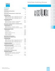
7TRANSFORMERSDistribution Dry Type
- Page 372 and 373:
7TRANSFORMERSTransformersDry Type D
- Page 374 and 375:
Distribution Dry Type TransformersS
- Page 376 and 377:
Distribution Dry Type TransformersT
- Page 378 and 379:
7TRANSFORMERSDistribution Dry Type
- Page 380 and 381:
7TRANSFORMERSDistribution Dry Type
- Page 382 and 383:
TransformersNEMA TP1 Energy Efficie
- Page 384 and 385:
7TRANSFORMERSTransformersSentron Ha
- Page 386 and 387:
Warehouse Stock TransformersType QS
- Page 388 and 389:
7TRANSFORMERSWarehouse Stock Transf
- Page 390 and 391:
Warehouse Stock TransformersBuck-Bo
- Page 392 and 393:
Buck-Boost TransformersSingle Phase
- Page 394 and 395:
Totally Integrated PowerSystem Over
- Page 396 and 397:
8POWERMONITORINGTotally Integrated
- Page 398 and 399:
Power Monitoring9330/9350 Power Qua
- Page 400 and 401:
Totally Integrated PowerCritical Pr
- Page 402 and 403:
Totally Integrated PowerCurrent & V
- Page 404 and 405:
NotesPOWERMONITORING88-12Siemens Po
- Page 406 and 407:
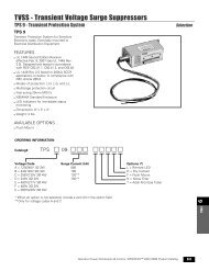
9TVSSTVSS - Transient Voltage Surge
- Page 408 and 409:
TVSS - Transient Voltage Surge Supp
- Page 410 and 411:
TVSS - Transient Voltage Surge Supp
- Page 412 and 413:
NotesTVSS99-8Siemens Power Distribu
- Page 414 and 415:
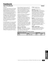
PanelboardsIntroductionThe new gene
- Page 416 and 417:
PanelboardsTrimOptionsStandard Trim
- Page 418 and 419:
10PANELBOARDSPanelboardsGeneral Spe
- Page 420 and 421:
PanelboardsGeneral SpecificationsTy
- Page 422 and 423:
PanelboardsDistributor StockPricing
- Page 424 and 425:
PanelboardsPanelboard Replacement,
- Page 426 and 427:
10PANELBOARDSSentron ® Panelboards
- Page 428 and 429:
PanelboardsCircuit Breaker / Lighti
- Page 430 and 431:
10PANELBOARDSPanelboardsCircuit Bre
- Page 432 and 433:
PanelboardsType 1 P1 Panelboard Mod
- Page 434 and 435:
PanelboardsType P1DimensionsType 1
- Page 436 and 437:
PanelboardsType P2 PanelboardsSelec
- Page 438 and 439:
PanelboardsType P2 PanelboardsBranc
- Page 440 and 441:
10PANELBOARDSPanelboardsType P2 Pan
- Page 442 and 443:
PanelboardsType P2 Panelboard Conne
- Page 444 and 445:
PanelboardsType P2 PanelboardsDimen
- Page 446 and 447:
PanelboardsType P3 PanelboardsPanel
- Page 448 and 449:
PanelboardsType P3 PanelboardsBranc
- Page 450 and 451:
PanelboardsType P3 PanelboardsTypic
- Page 452 and 453:
PanelboardsType P3 Panelboard Stand
- Page 454 and 455:
PanelboardsType P3 Panelboard Kits
- Page 456 and 457:
PanelboardsType P4 PanelboardsFeatu
- Page 458 and 459:
PanelboardsType P4 PanelboardsBranc
- Page 460 and 461:
PanelboardsPower and DistributionMa
- Page 462 and 463:
PanelboardsPower and DistributionBr
- Page 464 and 465:
Sentron ® PanelboardsModifications
- Page 466 and 467:
PanelboardsType P4 PanelboardsType
- Page 468 and 469:
PanelboardsPower and DistributionEn
- Page 470 and 471:
PanelboardsPower and DistributionAl
- Page 472 and 473:
PanelboardsPower and DistributionBr
- Page 474 and 475:
Sentron ® PanelboardsModifications
- Page 476 and 477:
PanelboardsModifications and Additi
- Page 478 and 479:
PanelboardsCircuit Breaker / Column
- Page 480 and 481:
10PANELBOARDSPanelboardsCircuit Bre
- Page 482 and 483:
Sentron ®PanelboardsTelephone and
- Page 484 and 485:
PanelboardsModifications and Additi
- Page 486 and 487:
NotesPANELBOARDS1010-74Siemens Powe
- Page 488 and 489:
11LIGHTINGCONTROLSLighting Controls
- Page 490 and 491:
11LIGHTINGCONTROLSLighting Controls
- Page 492 and 493:
11LIGHTINGCONTROLSLighting Controls
- Page 494 and 495:
11Lighting ControlsWeb Visualizatio
- Page 496 and 497:
11LIGHTINGCONTROLSLighting Controls
- Page 498 and 499:
NotesLIGHTINGCONTROLS1111-12Siemens
- Page 500 and 501:
12SWITCHBOARDSFront Connected Switc
- Page 502 and 503:
Integrated Power Systems Switchboar
- Page 504 and 505:
Integrated Power Systems Switchboar
- Page 506 and 507:
General Layout Information (Type SB
- Page 508 and 509:
General Layout Information (Type SB
- Page 510 and 511:
12SWITCHBOARDSGeneral Layout Inform
- Page 512 and 513:
12SWITCHBOARDSMulti-Metering Switch
- Page 514 and 515:
Multi-Metering SwitchboardsType SMM
- Page 516 and 517:
12SWITCHBOARDSSuper Blue Pennant Sw
- Page 518 and 519:
Super Blue Pennant SwitchboardsMain
- Page 520 and 521:
12Super Blue Pennant SwitchboardsCo
- Page 522 and 523:
Circuit Breaker, Fusible Applicatio
- Page 524 and 525:
12SWITCHBOARDSSwitchboard Replaceme
- Page 526 and 527:
13SWITCHGEARMedium Voltage Equipmen
- Page 528 and 529:
13SWITCHGEARMedium Voltage Equipmen
- Page 530 and 531:
Medium Voltage EquipmentGM-SG Ratin
- Page 532 and 533:
Medium Voltage EquipmentGM-SGTable
- Page 534 and 535:
13SWITCHGEARMedium Voltage Equipmen
- Page 536 and 537:
13SWITCHGEARMedium Voltage Equipmen
- Page 538 and 539:
Medium Voltage Equipment38 kV GM38
- Page 540 and 541:
13SWITCHGEARMedium Voltage Equipmen
- Page 542 and 543:
13SWITCHGEARMedium Voltage Equipmen
- Page 544 and 545:
13SWITCHGEARMedium Voltage Equipmen
- Page 546 and 547:
13Medium Voltage EquipmentMV Contro
- Page 548 and 549:
13SWITCHGEARPower Switching Centers
- Page 550 and 551:
13SWITCHGEARProtective Relays & SCA
- Page 552 and 553:
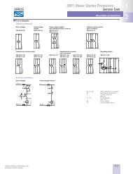
Protective Relays & SCADA SystemsSI
- Page 554 and 555:
13SWITCHGEARProtective Relays & SCA
- Page 556 and 557:
13SWITCHGEARReplacement Breakers &
- Page 558 and 559:
13SWITCHGEARField ServicesStart-up
- Page 560 and 561:
Field ServicesArc Flash StudyGenera
- Page 562 and 563:
Secondary Unit SubstationsTransform
- Page 564 and 565:
Secondary Unit SubstationsTransitio
- Page 566 and 567:
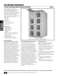
13SWITCHGEARLow Voltage SwitchgearT
- Page 568 and 569:
13SWITCHGEARLow Voltage SwitchgearT
- Page 570 and 571:
Low Voltage SwitchgearType WL Low V
- Page 572 and 573:
Low Voltage SwitchgearType WL Low V
- Page 574 and 575:
Low Voltage SwitchgearType WL Circu
- Page 576 and 577:
Low Voltage SwitchgearArc Flash Sol
- Page 578 and 579:
NotesSWITCHGEAR1313-54 Siemens Powe
- Page 580 and 581:
14BUSWAYSYSTEMSBusway Systems Overv
- Page 582 and 583:
14BUSWAYSYSTEMSSentron ® Busway Sy
- Page 584 and 585:
Sentron ® Straight Section BuswayA
- Page 586 and 587:
14BUSWAYSYSTEMSSentron ® Straight
- Page 588 and 589:
14BUSWAYSYSTEMSSentron ® Straight
- Page 590 and 591:
Sentron ®Hangers, Floor SupportsBu
- Page 592 and 593:
Sentron ® SLVB Bus PlugsBus Plugs
- Page 594 and 595:
Sentron ® Bus PlugsBus Plugs with
- Page 596 and 597:
Sentron ®Meter CentersBusway Syste
- Page 598 and 599:
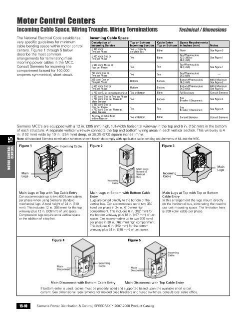
14BUSWAYSYSTEMSBusway SystemsNation
- Page 600 and 601: 14BUSWAYSYSTEMSBusway SystemsSentro
- Page 602 and 603: Busway SystemsTechnical DataTechnic
- Page 604 and 605: 14BUSWAYSYSTEMSBusway SystemsStraig
- Page 606 and 607: 14BUSWAYSYSTEMSBusway SystemsElbows
- Page 608 and 609: Busway SystemsOffsetsOffsets can be
- Page 610 and 611: Busway SystemsTeesTees are used to
- Page 612 and 613: Busway SystemsCenter Tap BoxesCente
- Page 614 and 615: 14BUSWAYSYSTEMSBusway SystemsReduce
- Page 616 and 617: 14BUSWAYSYSTEMSBusway SystemsHanger
- Page 618 and 619: 14BUSWAYSYSTEMSBusway SystemsHanger
- Page 620 and 621: Busway SystemsFlanged EndsFlanged e
- Page 622 and 623: Busway SystemsPanelboards and Meter
- Page 624 and 625: 14BUSWAYSYSTEMSBusway SystemsInstal
- Page 626 and 627: Busway Power DistributionXJ-L Plug
- Page 628 and 629: 14BUSWAYSYSTEMSBusway Power Distrib
- Page 630 and 631: 14BUSWAYSYSTEMSBusway Power Distrib
- Page 632 and 633: Busway Power DistributionXL-U ® Co
- Page 634 and 635: 14BUSWAYSYSTEMSBusway Power Distrib
- Page 636 and 637: 14BUSWAYSYSTEMSBusway Power Distrib
- Page 638 and 639: 14BUSWAYSYSTEMSBusway Mobile Indust
- Page 640 and 641: Busway Mobile Industrial PowerIndus
- Page 642 and 643: 15MOTOR CONTROLCENTERSTIASTAR Motor
- Page 644 and 645: Motor Control CentersQuality Featur
- Page 646 and 647: 15MOTOR CONTROLCENTERSTIASTAR Motor
- Page 648 and 649: Motor Control CentersStarter Rating
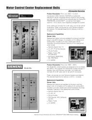
- Page 652 and 653: Motor Control Center Replacement Un
- Page 654 and 655: Motor Control Center Replacement Un
- Page 656 and 657: 16SPEEDFAX TM 2007-2008 Control Pro
- Page 658 and 659: Control ProductsNEMA & General Purp
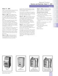
- Page 660 and 661: Manual ControlFractional HP Starter
- Page 662 and 663: Manual ControlSwitches , Class MMS
- Page 664 and 665: Manual ControlStarters and Switches
- Page 666 and 667: 16CONTROLPRODUCTSNEMA & GeneralPurp
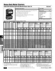
- Page 668 and 669: Heavy Duty Motor StartersSolid Stat
- Page 670 and 671: Heavy Duty Motor StartersAmbient Co
- Page 672 and 673: Combination Heavy Duty StartersNon-
- Page 674 and 675: Combination Heavy Duty StartersNon-
- Page 676 and 677: Combination Heavy Duty StartersFusi
- Page 678 and 679: Combination Heavy Duty StartersMCP
- Page 680 and 681: Combination Heavy Duty StartersMCP
- Page 682 and 683: Reversing Heavy Duty StartersAmbien
- Page 684 and 685: Combination Reversing Heavy Duty St
- Page 686 and 687: Two Speed Heavy Duty StartersConsta
- Page 688 and 689: Two Speed Heavy Duty StartersConsta
- Page 690 and 691: Combination Two Speed Heavy Duty St
- Page 692 and 693: Combination Two Speed Heavy Duty St
- Page 694 and 695: Combination Two Speed Heavy Duty St
- Page 696 and 697: Combination Two Speed Heavy Duty St
- Page 698 and 699: Heavy Duty Contractors3-Phase, Clas
- Page 700 and 701:
Reversing Heavy Duty ContactorsClas
- Page 702 and 703:
Overload RelaysSolid State and Ther
- Page 704 and 705:
16CONTROLPRODUCTSCurrent Sensitive
- Page 706 and 707:
16CONTROLPRODUCTSNEMA & GeneralPurp
- Page 708 and 709:
Duplex Heavy Duty ControllersCombin
- Page 710 and 711:
16CONTROLPRODUCTSNEMA & GeneralPurp
- Page 712 and 713:
Pump Control PanelsStandard Pump Pa
- Page 714 and 715:
Reduced Voltage Pump PanelsAuto Tra
- Page 716 and 717:
Vacuum Starter Pump PanelsWith Soli
- Page 718 and 719:
Reduced Voltage Heavy Duty Starters
- Page 720 and 721:
Reduced Voltage Heavy Duty Starters
- Page 722 and 723:
Lighting and Heating ControlElectri
- Page 724 and 725:
Lighting and Heating ControlCombina
- Page 726 and 727:
Lighting ControlMechanically and Ma
- Page 728 and 729:
16CONTROLPRODUCTSNEMA & GeneralPurp
- Page 730 and 731:
16CONTROLPRODUCTSNEMA & GeneralPurp
- Page 732 and 733:
Industrial Control Power Transforme
- Page 734 and 735:
Field Modification KitsClass 11 - 3
- Page 736 and 737:
Field Modification KitsNEMA, Lighti
- Page 738 and 739:
16CONTROLPRODUCTSField Modification
- Page 740 and 741:
Field Modification KitsNEMA, Reduce
- Page 742 and 743:
Field Modification KitsNEMA, Overlo
- Page 744 and 745:
Heavy Duty ControlNon-Combination E
- Page 746 and 747:
Combination Starter Enclosure KitsF
- Page 748 and 749:
Factory ModificationsSelectionOrder
- Page 750 and 751:
Factory ModificationsSelectionOrder
- Page 752 and 753:
Factory ModificationsDimensionsOrde
- Page 754 and 755:
Manual ControlClass SMF, MMSNEMA Ty
- Page 756 and 757:
Heavy Duty Motor StartersSolid Stat
- Page 758 and 759:
Reversing & Multispeed Heavy Duty S
- Page 760 and 761:
Heavy Duty ContactorsClass 40Full V
- Page 762 and 763:
Overload Relays & Current Sensitive
- Page 764 and 765:
Lighting & Heating ContactorsElectr
- Page 766 and 767:
Lighting ControlMechanically Latche
- Page 768 and 769:
Industrial Control Power Transforme
- Page 770 and 771:
RESRESETETHeavy Duty Motor Starters
- Page 772 and 773:
Combination Heavy Duty StartersEncl
- Page 774 and 775:
RESETReversing Heavy Duty Starters
- Page 776 and 777:
RESRESETETRESETOFFTRIPONCombination
- Page 778 and 779:
Combination Two Speed Heavy Duty St
- Page 780 and 781:
Duplex Heavy Duty ControllersClass
- Page 782 and 783:
Lighting ContactorsLE, CLM, CMDimen
- Page 784 and 785:
"X1X1X1X1"Heavy Duty Motor Starters
- Page 786 and 787:
Reversing Heavy Duty StartersClass
- Page 788 and 789:
Two Speed Heavy Duty StartersClass
- Page 790 and 791:
Reduced Voltage Starters & Pump Pan
- Page 792 and 793:
Reduced Voltage Starters & Pump Pan
- Page 794 and 795:
Heavy Duty Contactors and Reversing
- Page 796 and 797:
Duplex Heavy Duty ControllersClass
- Page 798 and 799:
Lighting and Heating ContactorsElec
- Page 800 and 801:
Lighting and Heating ContactorsMech
- Page 802 and 803:
16CONTROLPRODUCTSNEMA & GeneralPurp
- Page 804 and 805:
Manual ControlHeater Elements, Clas
- Page 806 and 807:
16CONTROLPRODUCTSNEMA & GeneralPurp
- Page 808 and 809:
16CONTROLPRODUCTSNEMA & GeneralPurp
- Page 810 and 811:
Replacement PartsStarters and Conta
- Page 812 and 813:
Replacement PartsLighting and Heati
- Page 814 and 815:
Definite Purpose ControlDefinite Pu
- Page 816 and 817:
SIRIUS Soft StartersIntroductionOve
- Page 818 and 819:
SIRIUS Soft StartersStandard Applic
- Page 820 and 821:
SIRIUS Soft StartersHigh Feature Ap
- Page 822 and 823:
Control ProductsEnclosed 3RW40Selec
- Page 824 and 825:
Control ProductsEnclosed 3RW403RW40
- Page 826 and 827:
Control ProductsEnclosed 3RW44Selec
- Page 828 and 829:
Control ProductsEnclosed 3RW44Selec
- Page 830 and 831:
Control ProductsEnclosed 3RW44Selec
- Page 832 and 833:
Control ProductsClass 73, 74Dimensi
- Page 834 and 835:
Pushbutton Units and Indicator Ligh
- Page 836 and 837:
Pushbutton Units and Indicator Ligh
- Page 838 and 839:
Pushbutton Units and Indicator Ligh
- Page 840 and 841:
Pushbutton Units and Indicator Ligh
- Page 842 and 843:
Pushbutton Units and Indicator Ligh
- Page 844 and 845:
Pushbutton Units and Indicator Ligh
- Page 846 and 847:
Pushbutton Units and Indicator Ligh
- Page 848 and 849:
Pushbutton Units and Indicator Ligh
- Page 850 and 851:
Pushbutton Units and Indicator Ligh
- Page 852 and 853:
Pushbutton Units and Indicator Ligh
- Page 854 and 855:
Pushbutton Units and Indicator Ligh
- Page 856 and 857:
Pushbutton Units and Indicator Ligh
- Page 858 and 859:
Pushbutton Units and Indicator Ligh
- Page 860 and 861:
Pushbutton Units and Indicator Ligh
- Page 862 and 863:
Pushbutton Units and Indicator Ligh
- Page 864 and 865:
Pushbutton Units and Indicator Ligh
- Page 866 and 867:
Pushbutton Units and Indicator Ligh
- Page 868 and 869:
Pushbutton Units and Indicator Ligh
- Page 870 and 871:
Pushbutton Units and Indicator Ligh
- Page 872 and 873:
Pushbutton Units and Indicator Ligh
- Page 874 and 875:
Pushbutton Units and Indicator Ligh
- Page 876 and 877:
Standby Power SystemsStandby Power
- Page 878 and 879:
Standby Power SystemsStandby Genera
- Page 880 and 881:
Standby Power SystemsTransfer Switc
- Page 882 and 883:
17STANDBYGENERATORSStandby Power Sy
- Page 884 and 885:
Standby Power SystemsManual Transfe
- Page 886 and 887:
TechnicalSiemens Design Assistant D
- Page 888 and 889:
18TECHNICALTechnicalTypes of Power
- Page 890 and 891:
18TECHNICALTechnicalGround Fault Pr
- Page 892 and 893:
TechnicalGround Fault Protection4-W
- Page 894 and 895:
TechnicalGround Fault ProtectionTyp
- Page 896 and 897:
18TECHNICALTechnicalGround Fault Pr
- Page 898 and 899:
18TECHNICALTechnicalSystem Analysis
- Page 900 and 901:
18TECHNICALTechnicalSeries-Connecte
- Page 902 and 903:
TechnicalHarmonics / K-factor Ratin
- Page 904 and 905:
18TECHNICALTechnicalTable 4AMotor F
- Page 906 and 907:
18TECHNICALMolded Case Circuit Brea
- Page 908 and 909:
18TECHNICALMolded Case Circuit Brea
- Page 910 and 911:
NOTESTECHNICAL1818-26Siemens Power
- Page 912 and 913:
Product IndexCatalog ProductNumber
- Page 914 and 915:
Product IndexCatalog ProductNumber
- Page 916 and 917:
Product IndexCatalog ProductNumber
- Page 918 and 919:
Product IndexCatalog ProductNumber
- Page 920 and 921:
Product IndexCatalog ProductNumber
- Page 922 and 923:
Product IndexCatalog ProductNumber
- Page 924 and 925:
Product IndexCatalog ProductNumber
- Page 926 and 927:
Product IndexCatalog ProductNumber
- Page 928 and 929:
Product IndexCatalog ProductNumber
- Page 930 and 931:
Product IndexCatalog ProductNumber
- Page 932 and 933:
Product IndexCatalogProductNumber C
- Page 934 and 935:
Product IndexCatalog ProductNumber
- Page 936 and 937:
Product IndexCatalog ProductNumber
- Page 938 and 939:
Product IndexCatalog ProductNumber
- Page 940:
Siemens Energy & Automation, Inc.33