- Page 1 and 2: GOVERNMENT OF MADHYA PRADESHDEPARTM
- Page 4 and 5: Branch(i) A special form of cast ir
- Page 6 and 7: A valve in which the closure to an
- Page 8 and 9: Sullage waste Water:Spent water fro
- Page 10 and 11: Laying:The approximate positions of
- Page 12 and 13: CHAPTER NO.1CAST IRON SOCKET AND SP
- Page 14 and 15: Socket and spigot pipes Class AWeig
- Page 16 and 17: 1.5 .4 Pipe shall be tested hydrost
- Page 18 and 19: 1.9.3 Mass (weight) of the various
- Page 20 and 21: Diameter (mm)Weight (approx) kgHeav
- Page 22 and 23: Diameter (mm)Weight (approx) kgHeav
- Page 24 and 25: 1.9.3.11 Cast iron plugs:-Diameter
- Page 26 and 27: 1.12.7 Caulking may be done with pn
- Page 28 and 29: 2.5 Thrust Blocks2.5.1 In case of b
- Page 30 and 31: 2.9.3 Should any test of the pipe l
- Page 32 and 33: CHAPTER NO.3CAST IRON PIPES AND SPE
- Page 34 and 35: 3.4.2.2 Cast iron flanged spigot:-R
- Page 36 and 37: 3.4.2.6 All flanged cast iron tees:
- Page 38 and 39: Diameter (mm)Weight (approx) kgHeav
- Page 40 and 41: Nominal diameterTable 2.3Refer Tabl
- Page 42 and 43: Table No.3.8DimensionWall thickness
- Page 44 and 45: CHAPTER NO. 4DUCTILE IRON PRESSURE
- Page 46 and 47: Nominal Diameter Outer diameter of
- Page 48 and 49: 4.3.2.4 Where the coating material
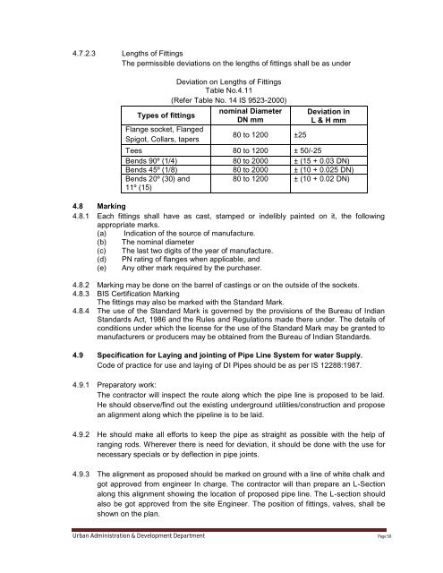
- Page 50 and 51: Nominal DiameterDN (mm)Table No. 4.
- Page 54 and 55: during the jointing operations. As
- Page 56 and 57: CHAPTER NO.5:UNPLASTICIZED PVC PIPE
- Page 58 and 59: NominaloutsideDiameter(Nominalsize)
- Page 60 and 61: 5.10 Handling and storage5.10.1 Bec
- Page 62 and 63: a)b) Size of the fitting and the ap
- Page 64 and 65: 5.14.5 Trench Bottom5.14.5.1 The tr
- Page 66 and 67: CHAPTER NO.6CAST IRON VALVES6.1 App
- Page 68 and 69: efore painting. All exposed machine
- Page 70 and 71: with the main. For large aqueduct p
- Page 72 and 73: 6.4.7 Nominal sizes :-6.4.7.1 The r
- Page 74 and 75: Table No.6.6Material for different
- Page 76 and 77: CHAPTER -7GALVANIZED IRON PIPES, SP
- Page 78 and 79: 7.4.2 Globe Valves- The globe valve
- Page 80 and 81: 7.6 Testing of valves:-7.6.1 Genera
- Page 82 and 83: NominalBoreDimensions and Nominal M
- Page 84 and 85: 7.10 Testing of Pipes :Following te
- Page 86 and 87: Nominal BoreMinimum Outside Minimum
- Page 88 and 89: 7.15.2.2 Taper Screw Plug TestSocke
- Page 90 and 91: 7.20.2 All pipes and fittings shall
- Page 92 and 93: S.NoTolerance and ovality is given
- Page 94 and 95: 8.7.2 The pipe shall be as uniform
- Page 96 and 97: directional changes within the tren
- Page 98 and 99: frequently used and in normal or sl
- Page 100 and 101: 8.22 Test to Establish Perfectibili
- Page 102 and 103:
8.26.6.3 PP Saddles8.26.6.3.1 The b
- Page 104 and 105:
g Bypass Pipe Carbon Steel IS1239(p
- Page 106 and 107:
9.4.1 Coupling Area of jointThis is
- Page 108 and 109:
Table No. 9.3Hydrostatic Design Pre
- Page 110 and 111:
polyester belts with a minimum widt
- Page 112 and 113:
9.19.4 Straight continues lengths o
- Page 114 and 115:
Table No. 10.2(Refer Table No.1 IS
- Page 116 and 117:
1592-2003. The tolerances on the in
- Page 118 and 119:
10.5.2.5 Weight of cast iron plain
- Page 120 and 121:
10.5.2.9 Weight of cast iron Plain
- Page 122 and 123:
10.8.1.1 Width- The width of the tr
- Page 124 and 125:
10.11.2 Cast Iron Detachable Joints
- Page 126 and 127:
shall be used between the straps an
- Page 128 and 129:
10.18.9.1 After the test has been c
- Page 130 and 131:
CHAPTER NO- 11SALT GLAZED STONEWRE
- Page 132 and 133:
11.3.2 Each pipe and fittings may a
- Page 134 and 135:
on each horizontal rail which is fi
- Page 136 and 137:
11.7.7 The joint with cast iron or
- Page 138 and 139:
CHAPTER NO- 12UNPLASTICIZED NON-PRE
- Page 140 and 141:
12.4 Dimensions of Pipes:12.4.1 Mea
- Page 142 and 143:
12.8 Trench:-(See Drawing No.3)12.8
- Page 144 and 145:
12.13.3 Care should be taken to lea
- Page 146 and 147:
12.17.6 HandlingFollowing Recommend
- Page 148 and 149:
12.17.10 Construction of backfill e
- Page 150 and 151:
CHAPTER - 13REINFORCED CEMENT CONCR
- Page 152 and 153:
Diameter ThicknessStrength Test Req
- Page 154 and 155:
Table 13.5(Refer Clause 8.2 IS 458
- Page 156 and 157:
efore the next pipe is laid. Adequa
- Page 158 and 159:
13.11.4 The water shall be filled t
- Page 160 and 161:
Chapter - 14SEWER APPURTENANCES14.1
- Page 162 and 163:
provided with cover of medium duty
- Page 164 and 165:
14.3.5.4.3 (c) By drop in previous
- Page 166 and 167:
14.5.3.4 Where the diameter of the
- Page 168 and 169:
14.7.4 Heavy reinforced concrete co
- Page 170 and 171:
14.11 By pass:By pass arrangements
- Page 172 and 173:
acetate paper, silt drums, ropes, i
- Page 174 and 175:
14.22. Automotive Suction Machine :
- Page 176 and 177:
14.25.3 Brick Masonry Chamber : Aft
- Page 178 and 179:
15.2.5 Lift: the vertical distance
- Page 180 and 181:
ensure that drilling has been done
- Page 182 and 183:
accepted deductions (stated as a pe
- Page 184 and 185:
described in IS 4031 (Part-5) : 198
- Page 186 and 187:
v) Cleat bolt of size M-10vi)vii)Se
- Page 188 and 189:
15.17.5.3 To protect persons from i
- Page 190 and 191:
15.17.5.19. Wherever a socket or co
- Page 192 and 193:
esults in unsuitable sub grade cond
- Page 194 and 195:
15.17.14.7 Clear out space shall be
- Page 196 and 197:
15.17.15.7.1 Ordinarily no surplus
- Page 198 and 199:
Water Supply pipes lines should be
- Page 200 and 201:
16.3.3 Failure to remove the ridge
- Page 202 and 203:
16.9.12 The cover shall be capable
- Page 204 and 205:
17.7 Development of tube-well with
- Page 206 and 207:
17.13.4 Fine enough to prevent the
- Page 208 and 209:
(iv) No. of slots per m 429(v) % Ar
- Page 210 and 211:
Annexure: ADRILLING OF TUBE WELL1.
- Page 212 and 213:
particularly those having clay or s
- Page 214 and 215:
5.3.2 The shape of the openings sho
- Page 216 and 217:
5.7.3.6.1 The contractor shall deve
- Page 218 and 219:
STRATACHATANNEXURE-2Mohalla/BastiNa
- Page 220 and 221:
LocationApparentResistivelyAB/2Inte
- Page 222 and 223:
GRAVEL PACKED TUBE WELLSGAVEL PACKE
- Page 224 and 225:
HAND PUMP PLATEFORMUrban Administra
- Page 226 and 227:
Urban Administration & Development
- Page 228 and 229:
Urban Administration & Development
- Page 230 and 231:
Urban Administration & Development
- Page 232 and 233:
Urban Administration & Development
- Page 234 and 235:
Urban Administration & Development
- Page 236 and 237:
Urban Administration & Development
- Page 238 and 239:
Urban Administration & Development
- Page 240 and 241:
Urban Administration & Development
- Page 242 and 243:
Urban Administration & Development
- Page 244 and 245:
Urban Administration & Development
- Page 246 and 247:
Urban Administration & Development
- Page 248 and 249:
Urban Administration & Development
- Page 250:
Urban Administration & Development