


You also want an ePaper? Increase the reach of your titles
YUMPU automatically turns print PDFs into web optimized ePapers that Google loves.
C Series: INLINE — Shaft Output<br />
C Series Motor Mounting Plate Option (Motor information required with Motor Adapter ME option)<br />
STOBER <strong>Servo</strong> <strong>Gear</strong>heads fit the motor of<br />
your choice with the appropriate motor<br />
mounting plate assembled between the<br />
motor and the gearhead.<br />
NOTE: When ordering a gearhead:<br />
• Specify the motor manufacturer and<br />
part number<br />
• Provide the motor drawing with<br />
dimensions, or specify the motor<br />
mounting dimensions (per the list<br />
shown at right)<br />
For a precise dimension on a specific motor,<br />
or for general assistance, we recommend<br />
you contact STOBER Technical Support.<br />
Customer Required Dimensions for Properly Sized Motor Mounting Plate<br />
Motor Mounting Plate Dimensions — mm(<strong>Gear</strong>head Part<br />
Number Specific) ME10 ME20 ME30 ME40 ME50<br />
Maximum Allowed Motor Shaft Dia. d2 19 32 38 48 60<br />
Minimum Allowed Motor Plate Thickness c * 21 24 26 35 43<br />
* Note that the c motor plate thickness is determined by the motor shaft length. The minimum motor plate thickness is the value listed.<br />
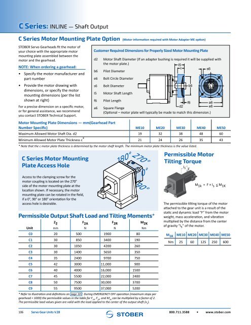
C Series Motor Mounting<br />
Plate Access Hole<br />
Access to the clamping screw for the<br />
motor coupling is located on the 270°<br />
side of the motor mounting plate at the<br />
location shown. If necessary, the motor<br />
mounting plate can be rotated in the field,<br />
if a 0°, 90° or 180° orientation for the<br />
access hole is desirable.<br />
Permissible Output Shaft Load and Tilting Moments*<br />
Z 2 F 2A F 2R M 2K<br />
Unit mm N N Nm<br />
C0 20 500 1900 80<br />
C1 30 850 3400 190<br />
C2 30 1050 4200 260<br />
C3 30 1400 5650 350<br />
C4 35 2400 9700 750<br />
C5 42 3000 11,000 900<br />
C6 40 4000 16,000 1500<br />
C7 45 5500 22,000 2400<br />
C8 50 7500 30,000 3700<br />
C9 55 9500 37,000 5200<br />
* Refer to illustration and definitions on page 107. During EMERGENCY OFF operation (maximum stops per<br />
gearhead = 1000) the permissible values in the table for F 2A<br />
, F 2R<br />
, and M 2K<br />
can be multiplied by a factor of 2.<br />
The permissible load values given are valid with the load applied to the center of the output shaft (x 2<br />
).<br />
d2<br />
b6<br />
e6<br />
s6<br />
I5<br />
f6<br />
a6<br />
Motor Shaft Diameter (If an adapter bushing is required it will be supplied with<br />
the motor plate.)<br />
I5<br />
c<br />
s6<br />
Pilot Diameter<br />
Bolt Circle Diameter<br />
Bolt Diameter<br />
Motor Shaft Length<br />
Pilot Length<br />
f6<br />
a6<br />
d2<br />
e6<br />
Square Flange<br />
(Optional – motor plate will typically be made to match this dimension.)<br />
180°270°<br />
90°<br />
0°<br />
Permissible Motor<br />
Tilting Torque<br />
I s<br />
F<br />
The permissible tilting torque of the motor<br />
attached to the gear unit is a result of the<br />
static and dynamic load “F” from the motor<br />
weight, mass acceleration, and vibration<br />
multiplied by the distance from the center<br />
of gravity “Is” of the motor.<br />
M 1K<br />
b6<br />
M 1k = F × I s < M 1K<br />
ME10 ME20 ME30 ME40 ME50<br />
Nm 25 60 125 250 600<br />
106 <strong>Servo</strong> <strong>Gear</strong> <strong>Units</strong> V.28<br />
800.711.3588 • www.stober.com


