


Create successful ePaper yourself
Turn your PDF publications into a flip-book with our unique Google optimized e-Paper software.
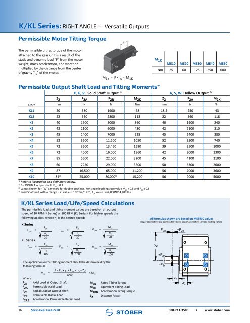
K/KL Series: RIGHT ANGLE — Versatile Outputs<br />
Permissible Motor Tilting Torque<br />
The permissible tilting torque of the motor<br />
attached to the gear unit is a result of the<br />
static and dynamic load “F” from the motor<br />
weight, mass acceleration, and vibration<br />
multiplied by the distance from the center<br />
of gravity “Is” of the motor.<br />
M 1k = F × I s < M 1K<br />
Is<br />
F<br />
M 1K<br />
ME10 ME20 ME30 ME40 ME50<br />
Nm 25 60 125 250 600<br />
Permissible Output Shaft Load and Tilting Moments*<br />
P, G, V Solid Shaft Output 1) A, S, W Hollow Output 2)<br />
Z 2 F 2A F 2R M 2K Z 2 F 2A M 2K<br />
Unit<br />
mm N N Nm mm N Nm<br />
KL1 20 380 1900 68 18.5 250 43<br />
KL2 22 560 2800 118 22 560 118<br />
K1 40 1900 5000 360 40 1900 240<br />
K2 42 2100 6000 430 42 2100 310<br />
K3 45 2400 7000 525 45 2400 380<br />
K4 52 3500 11,200 1050 52 3500 740<br />
K5 72 3500 13,450 1580 39 2500 1000<br />
K6 72 4000 16,000 1960 42 3000 1300<br />
K7 85 5500 22,000 3200 45 4100 2100<br />
K8 60 7250 29,000 3800 50 5300 2600<br />
K9 87 16,500 65,000 11,200 56 7000 3600<br />
K10 84 3) 25,000 80,000 3) 15,200 56 9000 5000<br />
* Refer to illustration and definitions below.<br />
1)<br />
For DOUBLE output shaft: F 2R<br />
x 0.7<br />
2)<br />
Values shown for “W” Style are for double bushings. For single bushings use value M 2K<br />
x 0.5 and F 2A<br />
x 0.5<br />
3)<br />
Solid Shaft unit with a Flange – Z 2<br />
value is 132mm/5.20”; F 2R<br />
value is 64,000N/14,400 lbs.<br />
K/KL Series Load/Life/Speed Calculations<br />
The permissible load and tilting moment values are based on an output<br />
speed of 20 RPM (K Series) or 100 RPM (KL Series). For higher speeds the<br />
following applies, where n 2<br />
is the desired speed:<br />
All<br />
K Series<br />
F2AX =<br />
KL Series<br />
F2AX =<br />
F 2A<br />
3 n 2<br />
20<br />
F 2A<br />
3 n 2<br />
100<br />
F 2RX<br />
=<br />
F2RX =<br />
F 2R<br />
3 n 2<br />
20<br />
F 2R<br />
3 n 2<br />
100<br />
M2KX =<br />
M2KX =<br />
M 2K<br />
3 n 2<br />
20<br />
M 2K<br />
3 n 2<br />
100<br />
formulas shown are based on METRIC values<br />
Upper case letters are permissible values. Lower case letters are for existing values.<br />
y 2<br />
–F 2a<br />
+F 2r<br />
+F 2a<br />
The application output tilting moment should be determined by the<br />
following formula:<br />
M 2A<br />
=<br />
2 • F 2a<br />
• y 2<br />
+ F 2rb<br />
• (x 2<br />
+ Z 2<br />
)<br />
1000<br />
< M 2K<br />
Where:<br />
F 2a Axial Load at Output Shaft<br />
M 2K Rated Tilting Torque<br />
F 2A Permissible Axial Load<br />
M 2k Equivalent Tilting Load<br />
F 2r Radial Load at Output Shaft<br />
M 2KB Acceleration Tilting Torque<br />
F 2R Permissible Radial Load<br />
Z 2 Distance Factor<br />
F 2RB Acceleration Permissible Radial Load<br />
–F 2r<br />
x 2<br />
z 2<br />
168 <strong>Servo</strong> <strong>Gear</strong> <strong>Units</strong> V.28<br />
800.711.3588 • www.stober.com


