


Create successful ePaper yourself
Turn your PDF publications into a flip-book with our unique Google optimized e-Paper software.
Technical Reference<br />
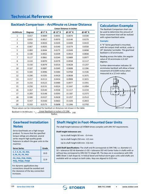
Backlash Comparison – ArcMinute vs Linear Distance<br />
Linear Distance in Inches<br />
ArcMinute Degrees @ 3” R @ 12” R @ 24” R @ 48” R<br />
1 0.017 0.0009 0.0035 0.0070 0.0140<br />
2 0.033 0.0017 0.0070 0.0140 0.0279<br />
3 0.050 0.0026 0.0105 0.0209 0.0419<br />
4 0.067 0.0035 0.0140 0.0279 0.0558<br />
5 0.083 0.0044 0.0175 0.0349 0.0698<br />
6 0.100 0.0052 0.0209 0.0419 0.0838<br />
7 0.117 0.0061 0.0244 0.0489 0.0977<br />
8 0.133 0.0070 0.0279 0.0558 0.1117<br />
9 0.150 0.0079 0.0314 0.0628 0.1257<br />
10 0.167 0.0087 0.0349 0.0698 0.1396<br />
11 0.183 0.0096 0.0384 0.0768 0.1536<br />
12 0.200 0.0105 0.0419 0.0838 0.1675<br />
13 0.217 0.0113 0.0454 0.0908 0.1815<br />
14 0.233 0.0122 0.0489 0.0977 0.1955<br />
15 0.250 0.0131 0.0524 0.1047 0.2094<br />
16 0.267 0.0140 0.0558 0.1117 0.2234<br />
17 0.283 0.0148 0.0593 0.1187 0.2373<br />
18 0.300 0.0157 0.0628 0.1257 0.2513<br />
19 0.317 0.0166 0.0663 0.1326 0.2653<br />
20 0.333 0.0175 0.0698 0.1396 0.2792<br />
These values can be interpolated for backlash or distances not shown in the table.<br />
Backlash in ArcMinutes =<br />
Linear Backlash in inches x 57.296<br />
( ) 60<br />
Radius<br />
Calculation Example<br />
The Backlash Comparison chart can<br />
be used to determine the amount of<br />
linear movement that will be realized<br />
with a given backlash value.<br />
Example:<br />
A “K” Series gearhead is mounted,<br />
with the output shaft vertical, under a<br />
24” diameter turntable. The gearhead<br />
backlash is 10 arcminutes.<br />
Reading across the table, the angular<br />
value of 10 arcminutes is 0.167<br />
degrees.<br />
Further determination indicates 10<br />
arcminutes backlash will allow a linear<br />
movement of 0.0349 inches when<br />
measured at a 12 inch radius.<br />
0.167°<br />
12”<br />
0.0349”<br />
<strong>Gear</strong>head Installation<br />
Notes<br />
<strong>Servo</strong> <strong>Gear</strong>heads are a high torque<br />
product. To insure that the specified<br />
torque ratings are attained, several<br />
series require high quality grade<br />
fasteners to attach the gear units to the<br />
machine:<br />
<strong>Servo</strong> Series<br />
C, F, K, KL, KS, KSS,<br />
P, PA, PE, PK, PKX<br />
PH, PHA, PHK, PHKX,<br />
PHQ, PHQA, PHQK<br />
Grade<br />
10.9<br />
12.9<br />
Shaft Height in Foot-Mounted <strong>Gear</strong> <strong>Units</strong><br />
The shaft height tolerance of STÖBER drives complies with DIN 747 requirements.<br />
Shaft height tolerances are:<br />
Up to shaft height 50 mm: -0.4 mm<br />
Up to shaft height 250 mm: -0.5 mm<br />
Up to shaft height 630 mm: -0.6 mm<br />
Solid Shaft Specifications: The shaft end fit corresponds to DIN 748; i.e. diameter d [<br />
50 = tolerance ISO k6 diameter d >50 = tolerance ISO m6 Center holes in shafts with or<br />
without key correspond to DIN 332 T2 shape DR. The keys are in accordance with DIN<br />
6885 Sheet 1 (tall shape A). In helical bevel and helical worm gear units solid shafts are<br />
available with an output on both sides. Keys are aligned to 0.03 mm.<br />
For dynamic applications key<br />
connections should be avoided and<br />
the clearance of the key connection<br />
increases.<br />
328 <strong>Servo</strong> <strong>Gear</strong> <strong>Units</strong> V.28 800.711.3588 • www.stober.com


