- Page 1 and 2:
Servo Gear Units Geared to a higher
- Page 3 and 4:
Geared to a higher standard Conten
- Page 5 and 6:
Geared to a higher standard Servic
- Page 7 and 8:
Unique STOBER Quality and Design Fe
- Page 9 and 10:
Overview Selection At-a-Glance Righ
- Page 11 and 12:
Overview Selection At-a-Glance RIGH
- Page 13 and 14:
Gearhead Sizing to your Specific Ap
- Page 15 and 16:
Overview Selection Options At-a-Gla
- Page 17 and 18:
Overview P/PA Series Motor Mounting
- Page 19 and 20:
Overview P/PA No Load Running Torqu
- Page 21 and 22:
Selection Data P2 Exact Ratio (i) O
- Page 23 and 24:
Selection Data Exact Ratio (i) P/PA
- Page 25 and 26:
Selection Data Exact Ratio (i) P/PA
- Page 27 and 28:
Selection Data Exact Ratio (i) P/PA
- Page 29 and 30:
Selection Data Exact Ratio (i) P/PA
- Page 31 and 32:
Selection Data Exact Ratio (i) P/PA
- Page 33 and 34:
Selection Data Exact Ratio (i) P/PA
- Page 35 and 36:
Selection Data Exact Ratio (i) P/PA
- Page 37 and 38:
Selection Data Exact Ratio (i) P/PA
- Page 39 and 40:
Selection Data Exact Ratio (i) P/PA
- Page 41 and 42:
Selection Data Exact Ratio (i) P/PA
- Page 43 and 44:
P9 Exact Ratio (i) Output Torque Mo
- Page 45 and 46:
Dimensional Data Large Input Option
- Page 47 and 48:
Overview Selection Options At-a-Gla
- Page 49 and 50:
Overview Note: Overview data is gen
- Page 51 and 52:
Overview PH Series Permissible Moto
- Page 53 and 54:
Selection Data Exact Ratio (i) Outp
- Page 55 and 56:
Selection Data Exact Ratio (i) Outp
- Page 57 and 58:
Selection Data Exact Ratio (i) Outp
- Page 59 and 60:
Selection Data Exact Ratio (i) Outp
- Page 61 and 62:
Selection Data Exact Ratio (i) Outp
- Page 63 and 64:
Selection Data Exact Ratio (i) Outp
- Page 65 and 66:
Selection Data Exact Ratio (i) Outp
- Page 67 and 68:
Selection Data Exact Ratio (i) Outp
- Page 69 and 70:
Selection Data Exact Ratio (i) Outp
- Page 71 and 72:
Selection Data Exact Ratio (i) Outp
- Page 73 and 74:
Selection Data Exact Ratio (i) Outp
- Page 75 and 76:
Selection Data Exact Ratio (i) Outp
- Page 77 and 78:
Selection Data Exact Ratio (i) Outp
- Page 79 and 80:
Selection Data Exact Ratio (i) Outp
- Page 81 and 82:
Selection Data Exact Ratio (i) Outp
- Page 83 and 84:
Selection Data Exact Ratio (i) Outp
- Page 85 and 86:
Selection Data Exact Ratio (i) Outp
- Page 87 and 88:
Dimensional Data Table 1 Dimensions
- Page 89 and 90:
Dimensional Data Table 1 Dimensions
- Page 91 and 92:
Dimensional Data Table 1 Dimensions
- Page 93 and 94:
Overview Selection Options At-a-Gla
- Page 95 and 96:
Overview Permissible Motor Tilting
- Page 97 and 98:
Selection Data Exact Ratio (i) Outp
- Page 99 and 100:
Selection Data Exact Ratio (i) Outp
- Page 101 and 102:
Dimensional Data PE with MAL Input
- Page 103 and 104:
Overview Selection Options At-a-Gla
- Page 105 and 106:
Overview C40 C50 C61 C71 C81 C91 2
- Page 107 and 108:
Overview C Series Lubrication Maint
- Page 109 and 110:
Selection Data Reducer Ratio (i) No
- Page 111 and 112:
Selection Data Reducer Ratio (i) No
- Page 113 and 114:
Selection Data Reducer Ratio (i) No
- Page 115 and 116:
Selection Data Reducer Ratio (i) No
- Page 117 and 118:
Selection Data Reducer Ratio (i) No
- Page 119 and 120:
Selection Data Reducer Ratio (i) No
- Page 121 and 122:
Selection Data Reducer Ratio (i) No
- Page 123 and 124:
Selection Data Reducer Ratio (i) No
- Page 125 and 126:
Selection Data Reducer Ratio (i) No
- Page 127 and 128:
Selection Data Reducer Ratio (i) No
- Page 129 and 130:
Selection Data Reducer Ratio (i) No
- Page 131 and 132:
Dimensional Data SMS Reducer Option
- Page 133 and 134:
Dimensional Data Table 1 Dimensions
- Page 135 and 136:
Dimensional Data Table 1 Dimensions
- Page 137 and 138:
Dimensional Data Table 1 Dimensions
- Page 139 and 140:
Dimensional Data Table 1 Dimensions
- Page 141 and 142:
Overview Selection Options At-a-Gla
- Page 143 and 144:
Overview F Series Motor Mounting Pl
- Page 145 and 146:
Overview Overhung Load Calculations
- Page 147 and 148:
Selection Data Reducer Ratio (i) No
- Page 149 and 150:
Selection Data Reducer Ratio (i) No
- Page 151 and 152:
Selection Data Reducer Ratio (i) No
- Page 153 and 154:
Selection Data Reducer Ratio (i) No
- Page 155 and 156:
Dimensional Data “V” Shaft Outp
- Page 157 and 158:
Dimensional Data “W” Double Bus
- Page 159 and 160:
Dimensional Data “A” Hollow Out
- Page 161 and 162:
Dimensional Data “S” Shrink Rin
- Page 163 and 164:
Overview Selection Options At-a-Gla
- Page 165 and 166:
Overview K51 K61 K71 K81 K91 K101 3
- Page 167 and 168:
Overview K/KL Series Output Options
- Page 169 and 170:
Selection Data Reducer Ratio (i) No
- Page 171 and 172:
Selection Data Reducer Ratio (i) No
- Page 173 and 174:
Selection Data Reducer Ratio (i) No
- Page 175 and 176:
Selection Data Reducer Ratio (i) No
- Page 177 and 178:
Selection Data Reducer Ratio (i) No
- Page 179 and 180:
Selection Data Reducer Ratio (i) No
- Page 181 and 182:
Selection Data Reducer Ratio (i) No
- Page 183 and 184:
Selection Data Reducer Ratio (i) No
- Page 185 and 186:
Selection Data Reducer Ratio (i) No
- Page 187 and 188:
Selection Data Reducer Ratio (i) No
- Page 189 and 190:
Selection Data Reducer Ratio (i) No
- Page 191 and 192:
Selection Data Reducer Ratio (i) No
- Page 193 and 194:
Dimensional Data KL Series with “
- Page 195 and 196:
Dimensional Data KL Series with “
- Page 197 and 198:
Dimensional Data KL Series with “
- Page 199 and 200:
Dimensional Data Table 1 K Series U
- Page 201 and 202:
Dimensional Data Table 1 K Series U
- Page 203 and 204:
Dimensional Data Table 1 K Series U
- Page 205 and 206:
Dimensional Data Table 1 K Series U
- Page 207 and 208:
Dimensional Data Table 1 K Series U
- Page 209 and 210:
Dimensional Data Table 1 K Series U
- Page 211 and 212:
Dimensional Data Table 1 K Series U
- Page 213 and 214:
Dimensional Data Optional “F” R
- Page 215 and 216:
Overview Selection Options At-a-Gla
- Page 217 and 218:
Overview PK Performance Overview PK
- Page 219 and 220:
Overview PKX/PK Series Motor Mounti
- Page 221 and 222:
Overview PKX/PK Output Bearing Opti
- Page 223 and 224:
Selection Data Exact Ratio (i) Nomi
- Page 225 and 226:
Selection Data Exact Ratio (i) Nomi
- Page 227 and 228:
Selection Data Exact Ratio (i) Nomi
- Page 229 and 230:
Selection Data Exact Ratio (i) Nomi
- Page 231 and 232:
Selection Data Exact Ratio (i) Nomi
- Page 233 and 234:
Selection Data Exact Ratio (i) Nomi
- Page 235 and 236:
Selection Data Exact Ratio (i) Nomi
- Page 237 and 238:
Selection Data Exact Ratio (i) Nomi
- Page 239 and 240:
Selection Data Reducer Ratio (i) No
- Page 241 and 242:
Selection Data Reducer Ratio (i) No
- Page 243 and 244:
Selection Data Reducer Ratio (i) No
- Page 245 and 246:
Dimensional Data PKX Series — Two
- Page 247 and 248:
Dimensional Data Motor Mounting Pla
- Page 249 and 250: Overview Selection Options At-a-Gla
- Page 251 and 252: Overview PHK Performance Overview S
- Page 253 and 254: Overview PHKX/PHK/PHQK Series Motor
- Page 255 and 256: Selection Data Exact Ratio (i) Nomi
- Page 257 and 258: Selection Data Exact Ratio (i) Nomi
- Page 259 and 260: Selection Data Exact Ratio (i) Nomi
- Page 261 and 262: Selection Data Exact Ratio (i) Nomi
- Page 263 and 264: Selection Data Exact Ratio (i) Nomi
- Page 265 and 266: Selection Data Exact Ratio (i) Nomi
- Page 267 and 268: Selection Data Exact Ratio (i) Nomi
- Page 269 and 270: Selection Data Exact Ratio (i) Nomi
- Page 271 and 272: Selection Data Exact Ratio (i) Nomi
- Page 273 and 274: Selection Data Exact Ratio (i) Nomi
- Page 275 and 276: Selection Data Exact Ratio (i) Nomi
- Page 277 and 278: Selection Data Exact Ratio (i) Nomi
- Page 279 and 280: Reducer Ratio (i) Nominal 1) M2N Ou
- Page 281 and 282: Selection Data Reducer Ratio (i) No
- Page 283 and 284: Selection Data Reducer Ratio (i) No
- Page 285 and 286: Selection Data Reducer Ratio (i) No
- Page 287 and 288: Selection Data Reducer Ratio (i) No
- Page 289 and 290: Selection Data Reducer Ratio (i) No
- Page 291 and 292: Selection Data Reducer Ratio (i) No
- Page 293 and 294: Dimensional Data Table 1 Dimensions
- Page 295 and 296: Dimensional Data Table 1 Dimensions
- Page 297 and 298: Dimensional Data Table 1 Dimensions
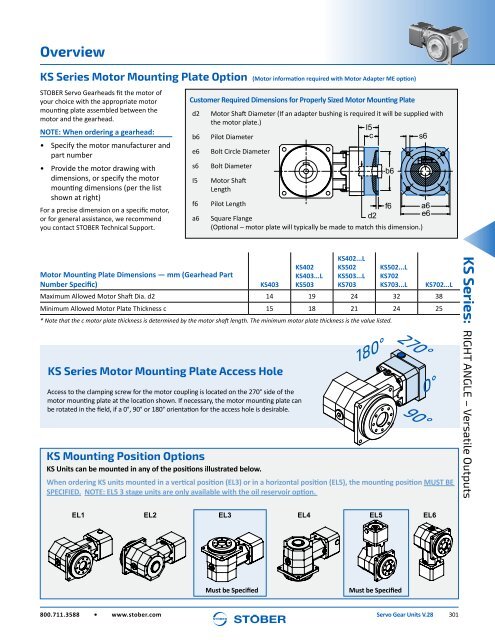
- Page 299: Overview Selection Options At-a-Gla
- Page 303 and 304: Selection Data Exact Ratio (i) Outp
- Page 305 and 306: Selection Data Exact Ratio (i) Outp
- Page 307 and 308: Dimensional Data Table 1 Dimensions
- Page 309 and 310: Dimensional Data Table 1 Dimensions
- Page 311 and 312: Dimensional Data Table 1 Dimensions
- Page 313 and 314: Overview IP69K/STAINLESS STEEL KSS
- Page 315 and 316: Overview IP69K/STAINLESS STEEL KSS
- Page 317 and 318: Selection Data IP69K/STAINLESS STEE
- Page 319 and 320: Selection Data IP69K/STAINLESS STEE
- Page 321 and 322: Dimensional Data IP69K/STAINLESS ST
- Page 323 and 324: Dimensional Data IP69K/STAINLESS ST
- Page 325 and 326: Dimensional Data IP69K/STAINLESS ST
- Page 327 and 328: Technical Reference C Series Solid
- Page 329 and 330: Technical Reference Values and Symb
- Page 331 and 332: Other Products from STOBER ServoSto
- Page 333: STOBER Servo Gear Units V.28