


You also want an ePaper? Increase the reach of your titles
YUMPU automatically turns print PDFs into web optimized ePapers that Google loves.
K/KL Series: RIGHT ANGLE — Versatile Outputs<br />
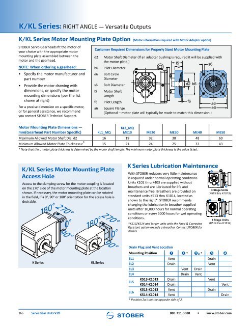
K/KL Series Motor Mounting Plate Option (Motor information required with Motor Adapter option)<br />
STOBER <strong>Servo</strong> <strong>Gear</strong>heads fit the motor of<br />
your choice with the appropriate motor<br />
mounting plate assembled between the<br />
motor and the gearhead.<br />
NOTE: When ordering a gearhead:<br />
• Specify the motor manufacturer and<br />
part number<br />
• Provide the motor drawing with<br />
dimensions, or specify the motor<br />
mounting dimensions (per the list<br />
shown at right)<br />
For a precise dimension on a specific motor,<br />
or for general assistance, we recommend<br />
you contact STOBER Technical Support.<br />
Customer Required Dimensions for Properly Sized Motor Mounting Plate<br />
d2<br />
b6<br />
e6<br />
s6<br />
I5<br />
f6<br />
a6<br />
Motor Shaft Diameter (If an adapter bushing is required it will be supplied with<br />
the motor plate.)<br />
Pilot Diameter<br />
Bolt Circle<br />
I5<br />
c<br />
s6<br />
Diameter<br />
Bolt Diameter<br />
d2 b6<br />
Motor Shaft<br />
Length<br />
Pilot Length<br />
f6<br />
a6<br />
Square Flange<br />
e6<br />
(Optional – motor plate will typically be made to match this dimension.)<br />
Motor Mounting Plate Dimensions —<br />
mm(<strong>Gear</strong>head Part Number Specific) KL1_MQ<br />
KL2_MQ<br />
ME10 ME20 ME30 ME40 ME50<br />
Maximum Allowed Motor Shaft Dia. d2 16 19 32 38 48 60<br />
Minimum Allowed Motor Plate Thickness c * 15 21 24 25 33 43<br />
* Note that the c motor plate thickness is determined by the motor shaft length. The minimum motor plate thickness is the value listed.<br />
K/KL Series Motor Mounting Plate<br />
Access Hole<br />
Access to the clamping screw for the motor coupling is located<br />
on the 270° side of the motor mounting plate at the location<br />
shown. If necessary, the motor mounting plate can be rotated<br />
in the field, if a 0°, 90° or 180° orientation for the access hole is<br />
desirable.<br />
180°<br />
270°<br />
0°<br />
90°<br />
180°<br />
270°<br />
0°<br />
K Series Lubrication Maintenance<br />
With STOBER reducers very little maintenance<br />
is required under normal operating conditions.<br />
<strong>Units</strong> K102 thru K403 are supplied without<br />
breathers and are lubricated for life and<br />
maintenance free. Breathers are provided on<br />
standard units K513 thru K1014, located as<br />
shown to the right*. STOBER recommends<br />
changing the lubrication in breather supplied<br />
units after 10,000 hours for normal operating<br />
conditions or every 5000 hours for wet operating<br />
conditions.<br />
*K513/K514 and larger units with the Food & Corrosion<br />
Resistant option exclude a breather. Contact STOBER for<br />
details.<br />
1<br />
2<br />
3<br />
3 Stage <strong>Units</strong><br />
(K513 thru K1013)<br />
1<br />
4<br />
2<br />
3<br />
4 Stage <strong>Units</strong><br />
(K514 thru K1014)<br />
K Series<br />
KL Series<br />
90°<br />
Drain Plug and Vent Location<br />
Mounting Position 1 2 * 2a * 3 4<br />
EL1 Vent Drain<br />
EL2 Drain Vent<br />
EL3 Vent Drain<br />
EL4 Drain Vent<br />
EL5<br />
K513-K1013 Drain Vent<br />
K514-K1014 Drain Vent<br />
EL6<br />
K513-K1013 Vent Drain<br />
K514-K1014 Vent Drain<br />
* Position 2a is on the opposite side of 2.<br />
166 <strong>Servo</strong> <strong>Gear</strong> <strong>Units</strong> V.28<br />
800.711.3588 • www.stober.com


