


You also want an ePaper? Increase the reach of your titles
YUMPU automatically turns print PDFs into web optimized ePapers that Google loves.
Overview<br />
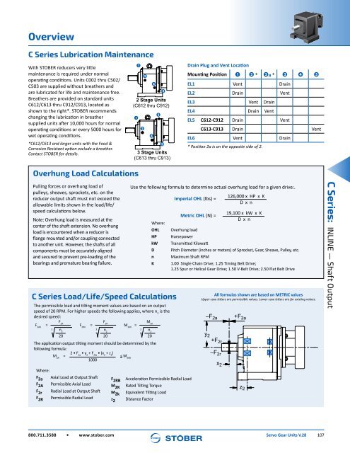
C Series Lubrication Maintenance<br />
With STOBER reducers very little<br />
maintenance is required under normal<br />
operating conditions. <strong>Units</strong> C002 thru C502/<br />
C503 are supplied without breathers and<br />
are lubricated for life and maintenance free.<br />
Breathers are provided on standard units<br />
C612/C613 thru C912/C913, located as<br />
shown to the right*. STOBER recommends<br />
changing the lubrication in breather<br />
supplied units after 10,000 hours for normal<br />
operating conditions or every 5000 hours for<br />
wet operating conditions.<br />
*C612/C613 and larger units with the Food &<br />
Corrosion Resistant option exclude a breather.<br />
Contact STOBER for details.<br />
1<br />
1<br />
2<br />
2<br />
4<br />
4<br />
5<br />
3<br />
2 Stage <strong>Units</strong><br />
(C612 thru C912)<br />
3<br />
3 Stage <strong>Units</strong><br />
(C613 thru C913)<br />
Drain Plug and Vent Location<br />
Mounting Position 1 2 * 2a * 3 4 5<br />
EL1 Vent Drain<br />
EL2 Drain Vent<br />
EL3 Vent Drain<br />
EL4 Drain Vent<br />
EL5 C612-C912 Drain Vent<br />
C613-C913 Drain Vent<br />
EL6 Vent Drain<br />
* Position 2a is on the opposite side of 2.<br />
Overhung Load Calculations<br />
Pulling forces or overhung load of<br />
pulleys, sheaves, sprockets, etc. on the<br />
reducer output shaft must not exceed the<br />
allowable limits shown in the load/life/<br />
speed calculations below.<br />
Note: Overhung load is measured at the<br />
center of the shaft extension. No overhung<br />
load is encountered when a reducer is<br />
flange mounted and/or coupling connected<br />
to another unit. However, the shafts of all<br />
components must be accurately aligned<br />
and secured to prevent pre-loading of the<br />
bearings and premature bearing failure.<br />
C Series Load/Life/Speed Calculations<br />
The permissible load and tilting moment values are based on an output<br />
speed of 20 RPM. For higher speeds the following applies, where n 2<br />
is the<br />
desired speed:<br />
F2AX =<br />
The application output tilting moment should be determined by the<br />
following formula:<br />
2 • F 2a<br />
• y 2<br />
+ F 2rb<br />
• (x 2<br />
+ z 2<br />
)<br />
M 2A<br />
= < M 2KB<br />
1000<br />
Where:<br />
F 2a<br />
F 2A<br />
F 2r<br />
F 2R<br />
F 2A<br />
3 n 2<br />
20<br />
F 2RX<br />
=<br />
Axial Load at Output Shaft<br />
Permissible Axial Load<br />
Radial Load at Output Shaft<br />
Permissible Radial Load<br />
F 2R<br />
3 n 2<br />
20<br />
F 2RB<br />
M 2K<br />
M 2k<br />
z 2<br />
Use the following formula to determine actual overhung load for a given drive:.<br />
M 2KX<br />
=<br />
M 2K<br />
3 n 2<br />
20<br />
Acceleration Permissible Radial Load<br />
Rated Tilting Torque<br />
Equivalent Tilting Load<br />
Distance Factor<br />
Where:<br />
OHL<br />
HP<br />
kW<br />
D<br />
n<br />
K<br />
Imperial OHL (lbs) =<br />
Metric OHL (N) =<br />
Overhung load<br />
Horsepower<br />
Transmitted Kilowatt<br />
Pitch Diameter (inches or meters) of Sprocket, <strong>Gear</strong>, Sheave, Pulley, etc.<br />
Maximum Shaft RPM<br />
1.00 Single Chain Drive; 1.25 Timing Belt Drive;<br />
1.25 Spur or Helical <strong>Gear</strong> Drive; 1.50 V-Belt Drive; 2.50 Flat Belt Drive<br />
All formulas shown are based on METRIC values<br />
Upper case letters are permissible values. Lower case letters are for existing values.<br />
y 2<br />
–F 2a<br />
+F 2r<br />
–F 2r<br />
x 2<br />
126,000 x HP x K<br />
D x n<br />
19,100 x kW x K<br />
D x n<br />
+F 2a<br />
z 2<br />
C Series: INLINE — Shaft Output<br />
800.711.3588 • www.stober.com <strong>Servo</strong> <strong>Gear</strong> <strong>Units</strong> V.28 107


