silo 3 - U.S. Department of Energy
silo 3 - U.S. Department of Energy
silo 3 - U.S. Department of Energy
Create successful ePaper yourself
Turn your PDF publications into a flip-book with our unique Google optimized e-Paper software.
. .-<br />
a ” 4.0;. .. 5.2.1 Sodium Lignosulfonate Supply<br />
Process Description for the Silo 3 Project<br />
Document No. 40430-RP-0003, Rev. 1<br />
Jacobs Project No. 35H19605<br />
September 5, 2003<br />
50 69<br />
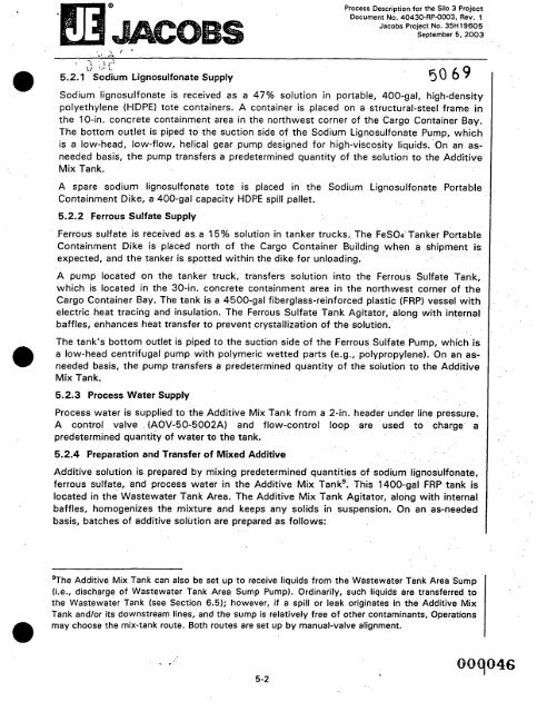
Sodium lignosulfonate is received as a 47% solution in portable, 400-ga1, high-density<br />
polyethylene (HDPE) tote containers. A container is placed on a structural-steel frame in<br />
the 10-in. concrete containment area in the northwest corner <strong>of</strong> the Cargo Container Bay.<br />
The bottom outlet is piped to the suction side <strong>of</strong> the Sodium Lignosulfonate Pump, which<br />
is a low-head, low-flow, helical gear pump designed for high-viscosity liquids. On an as-<br />
needed basis, the pump transfers a predetermined quantity <strong>of</strong> the solution to the Additive<br />
Mix Tank.<br />
A spare sodium lignosulfonate tote is placed in the Sodium Lignosulfonate Portable<br />
Containment Dike, a 400-gal capacity HDPE spill pallet.<br />
5.2.2 Ferrous Sulfate Supply<br />
Ferrous sulfate is received as a 15% solution in tanker trucks. The FeS04 Tanker Portable<br />
Containment Dike is placed north <strong>of</strong> the Cargo Container Building when a shipment is<br />
expected, and the tanker is spotted within the dike for unloading.<br />
A pump located on the tanker truck, transfers solution into the Ferrous Sulfate Tank,<br />
which is located in the 30-in. concrete containment area in the northwest corner <strong>of</strong> the<br />
Cargo Container Bay. The tank is a 4500-gal fiberglass-reinforced plastic (FRP) vessel with<br />
electric heat tracing and insulation. The Ferrous Sulfate Tank Agitator, along with internal<br />
baffles, enhances heat transfer to prevent crystallization <strong>of</strong> the solution.<br />
The tank’s bottom outlet is piped to the suction side <strong>of</strong> the Ferrous Sulfate Pump, which is<br />
a low-head centrifugal pump with polymeric wetted parts (e.g., polypropylene). On an as-<br />
needed basis, the pump transfers a predetermined quantity <strong>of</strong> the solution to the Additive<br />
Mix Tank.<br />
5.2.3 Process Water Supply<br />
Process water is supplied to the Additive Mix Tank from a 2-in. header under line pressure.<br />
A control valve (AOV-50-5002A) and flow-control loop are used to charge a<br />
predetermined quantity <strong>of</strong> water to the tank.<br />
5.2.4 Preparation and Transfer <strong>of</strong> Mixed Additive<br />
Additive solution is prepared by mixing predetermined quantities <strong>of</strong> sodium lignosulfonate,<br />
ferrous sulfate, and process water in the Additive Mix Tank’. This 1400-gal FRP tank is<br />
located in the Wastewater Tank Area. The Additive Mix Tank Agitator, along with internal<br />
baffles, homogenizes the mixture and keeps any solids in suspension. On an as-needed<br />
basis, batches <strong>of</strong> additive solution are prepared as follows:<br />
qhe Additive Mix Tank can also be set up to receive liquids from the Wastewater Tank Area Sump<br />
(i.e., discharge <strong>of</strong> Wastewater Tank Area Sump Pump). Ordinarily, such liquids are transferred to<br />
the Wastewater Tank (see Section 6.5); however, if a spill or leak originates in the Additive Mix<br />
Tank andlor its downstream lines, and the sump is relatively free <strong>of</strong> other contaminants, Operations<br />
may choose the mix-tank route. Both routes are set up by manual-valve alignment.<br />
5-2


