part 1: overview of cogeneration and its status in asia - Fire
part 1: overview of cogeneration and its status in asia - Fire
part 1: overview of cogeneration and its status in asia - Fire

Create successful ePaper yourself
Turn your PDF publications into a flip-book with our unique Google optimized e-Paper software.
State <strong>of</strong> art review <strong>of</strong> <strong>cogeneration</strong> 19<br />
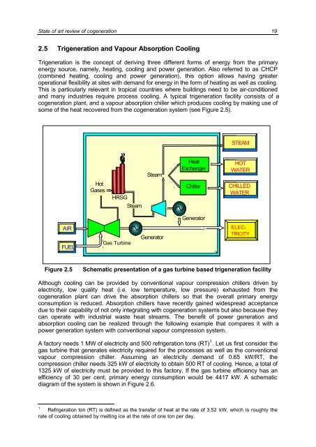
2.5 Trigeneration <strong>and</strong> Vapour Absorption Cool<strong>in</strong>g<br />
Trigeneration is the concept <strong>of</strong> deriv<strong>in</strong>g three different forms <strong>of</strong> energy from the primary<br />
energy source, namely, heat<strong>in</strong>g, cool<strong>in</strong>g <strong>and</strong> power generation. Also referred to as CHCP<br />
(comb<strong>in</strong>ed heat<strong>in</strong>g, cool<strong>in</strong>g <strong>and</strong> power generation), this option allows hav<strong>in</strong>g greater<br />
operational flexibility at sites with dem<strong>and</strong> for energy <strong>in</strong> the form <strong>of</strong> heat<strong>in</strong>g as well as cool<strong>in</strong>g.<br />
This is <strong>part</strong>icularly relevant <strong>in</strong> tropical countries where build<strong>in</strong>gs need to be air-conditioned<br />
<strong>and</strong> many <strong>in</strong>dustries require process cool<strong>in</strong>g. A typical trigeneration facility consists <strong>of</strong> a<br />
<strong>cogeneration</strong> plant, <strong>and</strong> a vapour absorption chiller which produces cool<strong>in</strong>g by mak<strong>in</strong>g use <strong>of</strong><br />
some <strong>of</strong> the heat recovered from the <strong>cogeneration</strong> system (see Figure 2.5).<br />
AIR<br />
FUEL<br />
Hot<br />
Gases<br />
HRSG<br />
GE Gas Frame Turb<strong>in</strong>e<br />
6<br />
Gas Turb<strong>in</strong>e<br />
Steam<br />
Steam<br />
Steam<br />
Turb<strong>in</strong>e<br />
Heat<br />
Exchanger<br />
Chiller<br />
Generator<br />
ELECTRICITY<br />
Generator<br />
STEAM<br />
HOT<br />
WATER<br />
CHILLED<br />
WATER<br />
ELEC-<br />
TRICITY<br />
Figure 2.5 Schematic presentation <strong>of</strong> a gas turb<strong>in</strong>e based trigeneration facility<br />
Although cool<strong>in</strong>g can be provided by conventional vapour compression chillers driven by<br />
electricity, low quality heat (i.e. low temperature, low pressure) exhausted from the<br />
<strong>cogeneration</strong> plant can drive the absorption chillers so that the overall primary energy<br />
consumption is reduced. Absorption chillers have recently ga<strong>in</strong>ed widespread acceptance<br />
due to their capability <strong>of</strong> not only <strong>in</strong>tegrat<strong>in</strong>g with <strong>cogeneration</strong> systems but also because they<br />
can operate with <strong>in</strong>dustrial waste heat streams. The benefit <strong>of</strong> power generation <strong>and</strong><br />
absorption cool<strong>in</strong>g can be realized through the follow<strong>in</strong>g example that compares it with a<br />
power generation system with conventional vapour compression system.<br />
A factory needs 1 MW <strong>of</strong> electricity <strong>and</strong> 500 refrigeration tons (RT) 1 . Let us first consider the<br />
gas turb<strong>in</strong>e that generates electricity required for the processes as well as the conventional<br />
vapour compression chiller. Assum<strong>in</strong>g an electricity dem<strong>and</strong> <strong>of</strong> 0.65 kW/RT, the<br />
compression chiller needs 325 kW <strong>of</strong> electricity to obta<strong>in</strong> 500 RT <strong>of</strong> cool<strong>in</strong>g. Hence, a total <strong>of</strong><br />
1325 kW <strong>of</strong> electricity must be provided to this factory. If the gas turb<strong>in</strong>e efficiency has an<br />
efficiency <strong>of</strong> 30 per cent, primary energy consumption would be 4417 kW. A schematic<br />
diagram <strong>of</strong> the system is shown <strong>in</strong> Figure 2.6.<br />
1<br />
Refrigeration ton (RT) is def<strong>in</strong>ed as the transfer <strong>of</strong> heat at the rate <strong>of</strong> 3.52 kW, which is roughly the<br />
rate <strong>of</strong> cool<strong>in</strong>g obta<strong>in</strong>ed by melt<strong>in</strong>g ice at the rate <strong>of</strong> one ton per day.