Jaguar XJ 1998 - JagRepair.com
Jaguar XJ 1998 - JagRepair.com
Jaguar XJ 1998 - JagRepair.com

You also want an ePaper? Increase the reach of your titles
YUMPU automatically turns print PDFs into web optimized ePapers that Google loves.
User Instructions<br />
<strong>XJ</strong> Series <strong>1998</strong><br />
Figure and Data Page Layout<br />
Figure Pages<br />
Each Figure represents a specific electrical system of the vehicle. The Figures are arranged numerically by system<br />
(01 – Power Distribution, 02 – Ground Distribution, etc.) with variations in the system identified by a numeral following<br />
a decimal point (01.1, 01.2, etc.). Refer to the Table of Contents for a <strong>com</strong>plete list of the Figures.<br />
The Figures 01 – Power Distribution detail the distribution of power to each of the systems. Numbered reference symbols<br />
refer the user to a specific Figure and from a specific Figure back to the Power Distribution Figures. This method eliminates<br />
the need to include detailed Power Distribution information on each of the Figures. Similarly, the Figure 02 – Ground Distribution<br />
details the ignition switched ground distribution. The reference symbols are defined on page 14.<br />
Each Figure appears on a right-hand page with a corresponding Data page to the left. The Figure and Data pages are folding<br />
pages. The user must fold out both pages in order to access all the information provided.<br />
Data Pages<br />
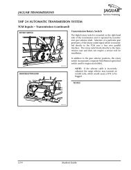
The Data page includes information to assist the user in identifying and locating <strong>com</strong>ponents, connectors and grounds.<br />
This information is supplemented by the illustrations in this front section of the book.<br />
When network data is required for the understanding of a particular circuit, the user is directed to the Appendix.<br />
Where circuits include a Control Module, Pin Out information is provided with values for “active” and “inactive” states.<br />
The values listed are approximately those that can be expected at the control module connector pins with all circuit connections<br />
made and all <strong>com</strong>ponents connected and fitted. “Active” means a load is applied or a switch is ON; “inactive”<br />
means a load is not applied or a switch is OFF. This information is provided to assist the user in understanding circuit<br />
operation and should be used FOR REFERENCE ONLY.<br />
12 DATE OF ISSUE: SEPTEMBER 1997