Jaguar XJ 1998 - JagRepair.com
Jaguar XJ 1998 - JagRepair.com
Jaguar XJ 1998 - JagRepair.com

Create successful ePaper yourself
Turn your PDF publications into a flip-book with our unique Google optimized e-Paper software.
User Instructions<br />
<strong>XJ</strong> Series <strong>1998</strong><br />
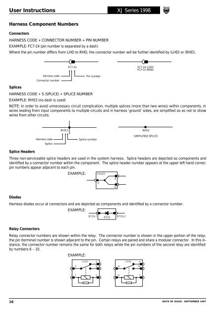
Harness Component Numbers<br />
Connectors<br />
HARNESS CODE + CONNECTOR NUMBER + PIN NUMBER<br />
EXAMPLE: FC7-24 (pin number is separated by a dash)<br />
Where the pin number differs from LHD to RHD, the connector number will be further identified by (LHD) or (RHD).<br />
FC7-24<br />
FC7-24 (LHD)<br />
FC7-15 (RHD)<br />
Harness code<br />
Connector number<br />
Pin number<br />
Splices<br />
HARNESS CODE + S (SPLICE) + SPLICE NUMBER<br />
EXAMPLE: RHS3 (no dash is used)<br />
NOTE: In order to avoid unnecessary circuit <strong>com</strong>plication, multiple splices (more than two wires) within <strong>com</strong>ponents, in<br />
wires leading from input <strong>com</strong>ponents to multiple circuits and in harness ‘ground’ sides, are simplified so as not to show<br />
wires from other circuits.<br />
RHS3<br />
RHS3<br />
Harness code<br />
Splice<br />
Splice number<br />
SIMPLIFIED SPLICE<br />
Splice Headers<br />
Three non-serviceable splice headers are used in the system harness. Splice headers are depicted as <strong>com</strong>ponents and<br />
identified by a connector number within the <strong>com</strong>ponent. The splice header number appears at the upper left hand corner;<br />
pin numbers appear adjacent to each pin.<br />
EXAMPLE: CA223<br />
-4<br />
-5<br />
-6<br />
Diodes<br />
Harness diodes occur at connectors and are depicted as <strong>com</strong>ponents and identified by a connector number.<br />
EXAMPLE:<br />
BT29-1<br />
BT29<br />
BT29-2<br />
Relay Connectors<br />
Relay connector numbers are shown within the relay. The connector number is shown in the upper portion of the relay;<br />
the pin (terminal) number is shown adjacent to the pin. Certain relays are paired and share a modular connector. In this instance,<br />
the connector number remains the same for both relays while the pin numbers of the second relay are identified<br />
by numbers 6 – 10.<br />
EXAMPLE:<br />
CA20<br />
4 CA20<br />
9<br />
3<br />
5<br />
8<br />
10<br />
1<br />
2<br />
6<br />
7<br />
16 DATE OF ISSUE: SEPTEMBER 1997