Manual - AEQ International
Manual - AEQ International
Manual - AEQ International

You also want an ePaper? Increase the reach of your titles
YUMPU automatically turns print PDFs into web optimized ePapers that Google loves.
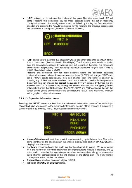
• “LPF”: allows you to activate the configured low pass filter (the associated LED willlight). Pressing this contextual key for three seconds opens the cut-off frequencyconfiguration menu: this configuration is accomplished by turning the first associatedencoder and pressing the “BACK” contextual key to return to the previous screen oncethis parameter is configured (between 1000 and 20000Hz).• “EQ”: allows you to activate the equalizer whose frequency response is shown at thattime on the screen (the associated LED will light). This frequency response is controlledfrom the associated encoders by working from left to right on the base, mid-range andtreble bands, respectively. The frequency deviation permitted ranges from -18dB to+18dB (the default value is +0dB).Pressing this contextual key for three seconds opens the equalizer advancedconfiguration menu, where 3 rows appears for base (“LOW”), mid-range (“MID”) andtreble (“HIG”) bands respectively. You can change from one band to another bypressing any of the three associated encoders. In the selected band (a flashing arrow isdisplayed), you can change the central frequency (“F(Hz)” column) by turning the firstencoder, the Q (“Q” column) by turning the second encoder and the gain (“G(dB)”column) by turning the third encoder. The “HPF”, “LPF” and “EQ” contextual keys in thisscreen allows you to activate filters and equalizer; the “BACK” key allows you to returnto the graphic configuration screen.3.4.3.1.3. Expanded information menu.Pressing the “NEXT” contextual key from the advanced information menu of an audio inputchannel will give you access to the advanced information section of that channel. It maintains astructure similar to the base menu. Information shown on this screen:• Name of the channel, in alphanumeric format containing up to 6 characters. This is thesame identifier as the one shown in the channel display. See section “2.1.1.3. Channeldisplay” in this manual.• Hardware corresponding to the audio input of this channel, in format HW: xx.yy, wherexx is the number of the virtual slot where this inputs/outputs module is installed, and yyis the audio channel of this inputs/outputs module. In stereo channels, yy represents theaudio channel corresponding to the left channel of the stereo pair. The right channelcorresponds to the number just above.• Channel type: mic/líne, analogue, digital or USB.• Indication of MONO or STEREO signal.<strong>AEQ</strong> CAPITOLUltra-compact digital audio mixer48