Manual - AEQ International
Manual - AEQ International
Manual - AEQ International

Create successful ePaper yourself
Turn your PDF publications into a flip-book with our unique Google optimized e-Paper software.
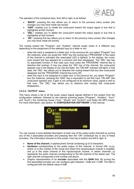
The operation of the contextual keys, from left to right, is as follows:• “BACK”: pressing this key allows you to return to the previous menu screen (thechanges you may have made are saved).• “ADD”: enables you to create the cross-point toward the output signal or bus that ishighlighted at that moment.• “DEL”: enables you to delete the cross-point toward the output signal or bus that ishighlighted at that moment.• “OK”: pressing this key allows you to return to the previous menu screen (the changesyou may have made are saved).The routing toward the “Program” and “Audition” internal buses works in a different waydepending on the assignment of the selected input to a fader or not:- when the input is assigned to a fader and, in the previous list, you select “Program” bus(for instance), when you press the “ADD” key the routing key (“PROGRAM” in this case)of the channel is activated (the associated LED is lighted). In the display, the crosspointtoward that bus appears for a moment and then dissappear. The “DEL” key hasno associated function in that case (you must press the “PROGRAM” channel key todeactive that routing). If now you press the “ON” key of the channel, the cross-pointappears now in the display (if you rise the fader, the “ON AIR” indicator will light); in thatcase, the “DEL” key allows you to deactive the routing toward that bus (the cross-pointdisappear and the “PROGRAM” channel key turns off).- when the input is not assigned to a fader and, in the previous list, you select “Program”bus (for instance), pressing the “ADD” key is equivalent to set that input “ON AIR” (thecross-point appears and, if gain is not configured at its minimum value, signal is sent tothat bus). The “DEL” key allows you to deactive that routing (the cross-pointdisappears).3.4.3.2. “OUTPUT“ menu.This menu shows a list of all the audio output logical signals defined in the system from theconfiguration software, followed by the internal summing buses (“Program”, “Audition”, “Aux1”and “Aux2”), the monitoring buses (“Cue”, “Studio” and “Control”) and finally the MPX buses.For more information, see section “4. CONFIGURATION SOFTWARE” in this manual.You can access a more detailed description of each one of the output audio channels by turningany of the 3 associated encoders and pressing then the “OK” contextual key or any of theseencoders. The information showed on this screen, from top to bottom and left to right, is:• Name of the channel, in alphanumeric format containing up to 6 characters.• Hardware corresponding to the audio output of this channel, in format HW: xx.yy,where xx is the number of the virtual slot where this inputs/outputs module is installed,and yy is the audio channel of this inputs/outputs module. In stereo channels, yyrepresents the audio channel corresponding to the left channel of the stereo pair. Theright channel corresponds to the number just above.• Graphic representation of an encoder associated with the GAIN field. By turning thefirst associated encoder you can configure gain between -12dB and +12dB. The field isconfigured with the default value of 0dB.<strong>AEQ</strong> CAPITOLUltra-compact digital audio mixer50