

Rover 214 & 414 Service and Repair Manual - Rover club
Rover 214 & 414 Service and Repair Manual - Rover club
Rover 214 & 414 Service and Repair Manual - Rover club

You also want an ePaper? Increase the reach of your titles
YUMPU automatically turns print PDFs into web optimized ePapers that Google loves.
3.8 Disconnecting multiplug from purge<br />
valve<br />
A Hose securing clip<br />
8 Disconnect the multiplug from the purge<br />
valve (see illustration).<br />
9 Release the securing clip <strong>and</strong> disconnect<br />
the hose from the purge valve.<br />
10 Note the fitted positions of the canister<br />
fuel <strong>and</strong> vent hoses, then use a suitable pair of<br />
pliers to release the retaining clips (where<br />
fitted) <strong>and</strong> disconnect both hoses from the<br />
canister.<br />
11 Release the securing strap <strong>and</strong> remove<br />
the canister/purge valve assembly.<br />
12 Refitting is the reverse of the removal<br />
procedure. Ensure that all hoses are correctly<br />
refitted <strong>and</strong>, where necessary, securely held<br />
by their retaining clips.<br />
Purge valve (charcoal canister<br />
separate) - renewal<br />
13 Disconnect the battery negative terminal<br />
then disconnect the wiring connector from the<br />
purge valve (see illustration).<br />
14 Release the retaining clips <strong>and</strong> disconnect<br />
the inlet <strong>and</strong> outlet hoses from the valve.<br />
15 Prise out the C-clip which secures the<br />
inlet hose adaptor to the mounting bracket,<br />
then withdraw the adaptor, noting the O-ring<br />
which is fitted between the adaptor <strong>and</strong> purge<br />
valve. Discard the O-ring which must be<br />
renewed.<br />
16 Undo the bolt securing the purge valve to<br />
its mounting bracket <strong>and</strong> remove the valve<br />
from the vehicle.<br />
17 Refitting is a reverse of the removal<br />
procedure. Use a new inlet hose adaptor Oring.<br />
Purge valve (on charcoal canister) -<br />
renewal<br />
18 Disconnect the battery negative lead.<br />
19 Disconnect the multiplug from the purge<br />
valve.<br />
20 Release the securing clip <strong>and</strong> disconnect<br />
the hose from the purge valve.<br />
21 Pull the valve from its location on the<br />
canister <strong>and</strong> discard its O-ring (see<br />
illustration).<br />
22 Refitting the valve is the reverse of the<br />
removal procedure, noting the following:<br />
a) Thoroughly clean the mating surfaces.<br />
b) Fit a new O-ring to the valve.<br />
c) Ensure all connections are secure.<br />
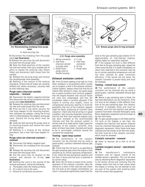
3.13 Purge valve assembly<br />
1 Wiring connector<br />
2 Inlet hose -<br />
charcoal canister<br />
to purge valve<br />
3 Outlet hose -<br />
purge valve to<br />
throttle housing<br />
4 C-clip<br />
5 Inlet hose<br />
connector<br />
6 O-ring<br />
7 Purge valve<br />
Exhaust emission control<br />
23 If the CO level reading is too high (or if any<br />
other symptom is encountered which causes<br />
you to suspect a fault in the exhaust emission<br />
control system), always check first that the air<br />
cleaner filter element is clean, the spark plugs<br />
are in good condition <strong>and</strong> correctly gapped,<br />
that the engine breather <strong>and</strong> vacuum hoses<br />
are clear <strong>and</strong> undamaged, <strong>and</strong> that the<br />
accelerator cable is correctly adjusted. If the<br />
engine is running very roughly, check its<br />
compression pressures, bearing in mind the<br />
possibility that one of the hydraulic tappets<br />
might be faulty, producing an incorrect valve<br />
clearance. Check also that all wiring is in good<br />
condition, with securely-fastened connectors,<br />
that the fuel filter (fuel-injected engines only)<br />
has been renewed at the recommended<br />
intervals <strong>and</strong> that the exhaust system is<br />
entirely free of air leaks which might upset the<br />
operation of the catalytic converter. Only<br />
when all these have been checked <strong>and</strong> found<br />
to be in serviceable condition should the<br />
converter be suspected.<br />
Testing - open-loop system<br />
24 The performance of the catalytic<br />
converter can be checked only by using a<br />
good-quality, carefully-calibrated exhaust gas<br />
analyser.<br />
25 Check that the CO level is as specified at<br />
the gas-sampling pipe when the engine is fully<br />
warmed-up to normal operating temperature.<br />
If not, check the fuel <strong>and</strong> ignition systems until<br />
the fault is found <strong>and</strong> the level is restored to<br />
its correct value.<br />
26 Once the CO level is known to be correct<br />
upstream of the catalytic converter, take the<br />
vehicle on a brisk 4-mile road test <strong>and</strong> check<br />
the CO level at the tailpipe immediately on<br />
return. It should be significantly lower than the<br />
1689 <strong>Rover</strong> <strong>214</strong> & <strong>414</strong> Updated Version 09/97<br />
Emission control systems 4D•3<br />
3.21 Renew purge valve O-ring (arrowed)<br />
level at the gas-sampling pipe (below 0.5 %<br />
approximately on fuel-injected engines,<br />
slightly higher on carburettor engines).<br />
27 If the tailpipe CO level is little different<br />
from that at the gas-sampling pipe, repeat the<br />
check ensuring that it is made immediately on<br />
return from road test or the converter may not<br />
be at normal operating temperature <strong>and</strong> will<br />
not have reached its peak conversion<br />
efficiency. If the results are the same, the<br />
catalytic converter is proven faulty <strong>and</strong> must<br />
be renewed.<br />
Testing - closed-loop system<br />
28 The performance of the catalytic<br />
converter can be checked only by using a<br />
good-quality, carefully-calibrated exhaust gas<br />
analyser.<br />
29 Where a gas-sampling pipe is fitted, the<br />
test described above can be carried out. If the<br />
CO level at the tailpipe is little different from<br />
that at the gas-sampling pipe, the catalytic<br />
converter is probably faulty <strong>and</strong> must be<br />
renewed, once the fuel-injection <strong>and</strong> ignition<br />
systems have been checked thoroughly using<br />
<strong>Rover</strong> diagnostic equipment <strong>and</strong> are known to<br />
be free from faults.<br />
30 If a gas-sampling pipe is not fitted <strong>and</strong> the<br />
CO level at the tailpipe is too high, the<br />
complete fuel-injection <strong>and</strong> ignition systems<br />
must be checked thoroughly by using <strong>Rover</strong><br />
diagnostic equipment. Once these have been<br />
checked <strong>and</strong> are known to be free from faults,<br />
the fault must be in the catalytic converter,<br />
which must be renewed.<br />
Catalytic converter - renewal<br />
31 Refer to Section 18 in Part A of this<br />
Chapter.<br />
Lambda (oxygen) sensor - operational<br />
check<br />
32 The manufacturer’s maintenance<br />
schedule calls for regular checks of the<br />
lambda sensor’s operation. This can be done<br />
only by attaching <strong>Rover</strong> diagnostic equipment<br />
to the sensor wiring <strong>and</strong> checking that the<br />
voltage varies from low to high values when<br />
the engine is running. Do not attempt to test<br />
any part of the system with anything other<br />
than the correct test equipment.<br />
4D