

Rover 214 & 414 Service and Repair Manual - Rover club
Rover 214 & 414 Service and Repair Manual - Rover club
Rover 214 & 414 Service and Repair Manual - Rover club

You also want an ePaper? Increase the reach of your titles
YUMPU automatically turns print PDFs into web optimized ePapers that Google loves.
2B•6 Engine removal <strong>and</strong> general overhaul procedures<br />
7.15 Grinding-in a valve seat<br />
even the renewal of the valve or seat insert is<br />
required.<br />
14 Valve grinding is carried out as follows.<br />
Place the cylinder head upside down on a<br />
bench.<br />
15 Smear a trace of (the appropriate grade of)<br />
valve-grinding compound on the seat face <strong>and</strong><br />
press a suction grinding tool onto the valve<br />
head. With a semi-rotary action, grind the valve<br />
head to its seat, lifting the valve occasionally to<br />
redistribute the grinding compound (see<br />
illustration). A light spring placed under the<br />
valve head will greatly ease this operation.<br />
16 If coarse grinding compound is being<br />
used, work only until a dull, matt even surface<br />
is produced on both the valve seat <strong>and</strong> the<br />
valve, then wipe off the used compound <strong>and</strong><br />
repeat the process with fine compound. When<br />
a smooth unbroken ring of light grey matt<br />
finish is produced on both the valve <strong>and</strong> seat,<br />
the grinding operation is complete. Do not<br />
grind in the valves any further than absolutely<br />
necessary, or the seat will be prematurely<br />
sunk into the cylinder head.<br />
17 To check that the seat has not been overground,<br />
measure the valve stem installed<br />
height, as described in paragraph 7.<br />
18 When all the valves have been ground-in,<br />
carefully wash off all traces of grinding<br />
compound using paraffin or a suitable solvent.<br />
Valve components<br />
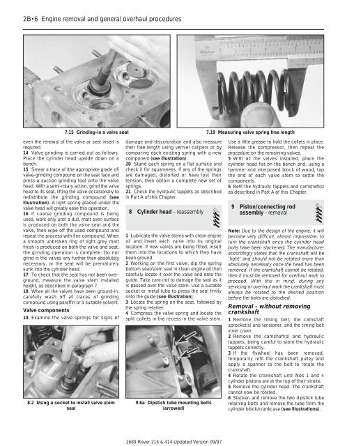
19 Examine the valve springs for signs of<br />
8.2 Using a socket to install valve stem<br />
seal<br />
damage <strong>and</strong> discoloration <strong>and</strong> also measure<br />
their free length using vernier calipers or by<br />
comparing each existing spring with a new<br />
component (see illustration).<br />
20 St<strong>and</strong> each spring on a flat surface <strong>and</strong><br />
check it for squareness. If any of the springs<br />
are damaged, distorted or have lost their<br />
tension, then obtain a complete new set of<br />
springs.<br />
21 Check the hydraulic tappets as described<br />
in Part A of this Chapter.<br />
8 Cylinder head - reassembly<br />
4<br />
1 Lubricate the valve stems with clean engine<br />
oil <strong>and</strong> insert each valve into its original<br />
location. If new valves are being fitted, insert<br />
them into the locations to which they have<br />
been ground.<br />
2 Working on the first valve, dip the spring<br />
bottom seat/stem seal in clean engine oil then<br />
carefully locate it over the valve <strong>and</strong> onto the<br />
guide. Take care not to damage the seal as it<br />
is passed over the valve stem. Use a suitable<br />
socket or metal tube to press the seal firmly<br />
onto the guide (see illustration).<br />
3 Locate the spring on the seat, followed by<br />
the spring retainer.<br />
4 Compress the valve spring <strong>and</strong> locate the<br />
split collets in the recess in the valve stem.<br />
9.6a Dipstick tube mounting bolts<br />
(arrowed)<br />
1689 <strong>Rover</strong> <strong>214</strong> & <strong>414</strong> Updated Version 09/97<br />
7.19 Measuring valve spring free length<br />
Use a little grease to hold the collets in place.<br />
Release the compressor, then repeat the<br />
procedure on the remaining valves.<br />
5 With all the valves installed, place the<br />
cylinder head flat on the bench <strong>and</strong>, using a<br />
hammer <strong>and</strong> interposed block of wood, tap<br />
the end of each valve stem to settle the<br />
components.<br />
6 Refit the hydraulic tappets <strong>and</strong> camshaft(s)<br />
as described in Part A of this Chapter.<br />
9 Piston/connecting rod<br />
assembly - removal 4<br />
Note: Due to the design of the engine, it will<br />
become very difficult, almost impossible, to<br />
turn the crankshaft once the cylinder head<br />
bolts have been slackened. The manufacturer<br />
accordingly states that the crankshaft will be<br />
‘tight’ <strong>and</strong> should not be rotated more than<br />
absolutely necessary once the head has been<br />
removed. If the crankshaft cannot be rotated,<br />
then it must be removed for overhaul work to<br />
proceed. With this in mind, during any<br />
servicing or overhaul work the crankshaft must<br />
always be rotated to the desired position<br />
before the bolts are disturbed.<br />
Removal - without removing<br />
crankshaft<br />
1 Remove the timing belt, the camshaft<br />
sprocket(s) <strong>and</strong> tensioner, <strong>and</strong> the timing belt<br />
inner cover.<br />
2 Remove the camshaft(s) <strong>and</strong> hydraulic<br />
tappets, being careful to store the hydraulic<br />
tappets correctly.<br />
3 If the flywheel has been removed,<br />
temporarily refit the crankshaft pulley <strong>and</strong><br />
apply a spanner to the bolt to rotate the<br />
crankshaft.<br />
4 Rotate the crankshaft until Nos 1 <strong>and</strong> 4<br />
cylinder pistons are at the top of their stroke.<br />
5 Remove the cylinder head. The crankshaft<br />
cannot now be rotated.<br />
6 Slacken <strong>and</strong> remove the two dipstick tube<br />
retaining bolts <strong>and</strong> remove the tube from the<br />
cylinder block/crankcase (see illustrations).