

Rover 214 & 414 Service and Repair Manual - Rover club
Rover 214 & 414 Service and Repair Manual - Rover club
Rover 214 & 414 Service and Repair Manual - Rover club

You also want an ePaper? Increase the reach of your titles
YUMPU automatically turns print PDFs into web optimized ePapers that Google loves.
16.7 Disconnect Lucar connection <strong>and</strong><br />
multiplug (A), SRS warning light (B),<br />
remove control unit securing screws (C)<br />
<strong>and</strong> release SRS warning light wiring<br />
harness (D)<br />
7 Disconnect the control unit multiplug <strong>and</strong><br />
Lucar connection (see illustration).<br />
8 Detach the SRS warning light from the<br />
steering wheel.<br />
9 Remove the three screws securing the<br />
control unit to the steering wheel.<br />
10 Release the SRS warning light wiring<br />
harness <strong>and</strong> remove the control unit.<br />
Refitting<br />
11 Refit the control unit by reversing the<br />
removal procedure, noting the following:<br />
a) If the control unit is to be renewed, then<br />
the bar code on the new item must be<br />
recorded by your <strong>Rover</strong> dealer.<br />
b) Take care to ensure that wiring is not<br />
trapped between mating surfaces.<br />
c) Observe the specified torque wrench<br />
setting when tightening the control unit<br />
retaining screws (TX20 Torx type) <strong>and</strong><br />
take care not to cross-thread them.<br />
d) Refit the airbag unit, carrying out the<br />
system check.<br />
Slip ring<br />
Removal<br />
12 Set the steering in the straight-ahead<br />
position.<br />
13 Remove the airbag unit.<br />
14 Refer to Chapter 10 <strong>and</strong> remove the<br />
steering wheel, followed by the steering<br />
column nacelle.<br />
15 Disconnect the airbag wiring harness<br />
multiplug from the underside of the slip ring<br />
(see illustration).<br />
16 Remove the four screws securing the ring<br />
to the column switch assembly <strong>and</strong> remove<br />
the ring from the vehicle.<br />
Refitting<br />
17 Refit the slip ring by reversing the removal<br />
procedure, noting the following:<br />
a) If the slip ring is to be renewed, then the<br />
bar code on the new item must be<br />
recorded by your <strong>Rover</strong> dealer.<br />
16.15 Disconnect SRS wiring harness<br />
multiplug (A), remove slip ring securing<br />
screws (B) <strong>and</strong> remove slip ring (C)<br />
b) Take care to ensure that wiring is not<br />
trapped between mating surfaces.<br />
c) Refit the airbag unit, carrying out the<br />
system check.<br />
Airbag link harness<br />
Removal<br />
18 Remove the ignition key <strong>and</strong> wait at least<br />
ten minutes to allow the SRS system backup<br />
circuit to fully discharge. Disconnect both<br />
battery leads, earth lead first, to avoid<br />
accidental detonation of the airbag.<br />
19 Remove the airbag unit.<br />
20 Set the steering in the straight-ahead<br />
position then lock the steering column in its<br />
lowest position.<br />
21 Remove the five fusebox cover<br />
securing screws <strong>and</strong> release the cover from<br />
the facia.<br />
22 Remove the three screws securing the<br />
lower half of the steering column shroud <strong>and</strong><br />
manoeuvre the lower half of the shroud clear<br />
of the column.<br />
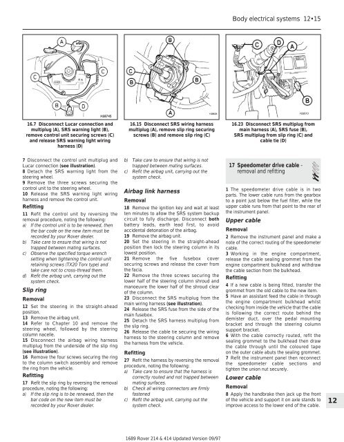
23 Disconnect the SRS multiplug from the<br />
main wiring harness (see illustration).<br />
24 Release the SRS fuse from the side of the<br />
main fusebox.<br />
25 Detach the SRS harness multiplug from<br />
the slip ring.<br />
26 Release the cable tie securing the wiring<br />
harness to the steering column <strong>and</strong> remove<br />
the harness from the vehicle.<br />
Refitting<br />
27 Refit the harness by reversing the removal<br />
procedure, noting the following:<br />
a) Take care to ensure that the harness is<br />
correctly routed <strong>and</strong> not trapped between<br />
mating surfaces.<br />
b) Check all wiring connectors are firmly<br />
fastened<br />
c) Refit the airbag unit, carrying out the<br />
system check.<br />
1689 <strong>Rover</strong> <strong>214</strong> & <strong>414</strong> Updated Version 09/97<br />
Body electrical systems 12•15<br />
16.23 Disconnect SRS multiplug from<br />
main harness (A), SRS fuse (B),<br />
SRS multiplug from slip ring (C) <strong>and</strong><br />
cable tie (D)<br />
17 Speedometer drive cable -<br />
removal <strong>and</strong> refitting 2<br />
1 The speedometer drive cable is in two<br />
parts. The lower cable runs from the gearbox<br />
to a point just below the fuel filter, while the<br />
upper cable runs from that point to the rear of<br />
the instrument panel.<br />
Upper cable<br />
Removal<br />
2 Remove the instrument panel <strong>and</strong> make a<br />
note of the correct routing of the speedometer<br />
cable.<br />
3 Working in the engine compartment,<br />
release the cable sealing grommet from the<br />
engine compartment bulkhead <strong>and</strong> withdraw<br />
the cable section from the bulkhead.<br />
Refitting<br />
4 If a new cable is being fitted, transfer the<br />
grommet from the old cable to the new item.<br />
5 Have an assistant feed the cable in through<br />
the engine compartment bulkhead whilst<br />
checking from inside the vehicle that the cable<br />
is following the correct route behind the<br />
demister duct, over the pedal mounting<br />
bracket <strong>and</strong> through the steering column<br />
support bracket.<br />
6 With the cable correctly routed, refit the<br />
sealing grommet to the bulkhead then draw<br />
the cable through until the coloured tape<br />
on the outer cable abuts the sealing grommet.<br />
7 Refit the instrument panel then reconnect<br />
the speedometer cable sections <strong>and</strong><br />
tighten the union nut securely.<br />
Lower cable<br />
Removal<br />
8 Apply the h<strong>and</strong>brake then jack up the front<br />
of the vehicle <strong>and</strong> support it on axle st<strong>and</strong>s to<br />
improve access to the lower end of the cable.<br />
12