

Rover 214 & 414 Service and Repair Manual - Rover club
Rover 214 & 414 Service and Repair Manual - Rover club
Rover 214 & 414 Service and Repair Manual - Rover club

Create successful ePaper yourself
Turn your PDF publications into a flip-book with our unique Google optimized e-Paper software.
12 Valve clearances -<br />
general information<br />
1 It is necessary for a clearance to exist<br />
between the tip of each valve stem <strong>and</strong> the<br />
valve operating mechanism. This allows for<br />
expansion of the various engine components<br />
as the engine reaches normal operating<br />
temperature.<br />
2 On most older engine designs, this meant<br />
that the valve clearances (also known as<br />
‘tappet’ clearances) had to be checked <strong>and</strong><br />
adjusted regularly. If the clearances were too<br />
slack, the engine would be very noisy, its<br />
power output would suffer <strong>and</strong> its fuel<br />
consumption would increase. Conversely, if<br />
the clearances were too tight, the engine’s<br />
power output would be reduced <strong>and</strong> the<br />
valves <strong>and</strong> their seats could be severely<br />
damaged.<br />
3 The engines covered in this <strong>Manual</strong> employ<br />
hydraulic tappets which use engine oil<br />
pressure to automatically take up the<br />
clearance between each camshaft lobe <strong>and</strong><br />
its respective valve stem. This means that<br />
there is no need for regular checking <strong>and</strong><br />
inspection of the valve clearances, but it is<br />
essential that only good quality oil of the<br />
recommended viscosity <strong>and</strong> specification is<br />
used in the engine <strong>and</strong> that this oil is<br />
scrupulously changed at the recommended<br />
intervals. If this advice is not followed, the<br />
oilways <strong>and</strong> tappets may become clogged<br />
with particles of dirt or deposits of burnt<br />
engine oil, so that the system cannot work<br />
properly. Ultimately, one or more of the<br />
tappets may fail <strong>and</strong> expensive repairs may<br />
be required.<br />
4 On starting the engine from cold, there will<br />
be a slight delay while full oil pressure builds<br />
up in all parts of the engine, especially in the<br />
tappets. The valve clearances, therefore, may<br />
well rattle for about 10 seconds or so <strong>and</strong><br />
then quieten. This is a normal state of affairs<br />
<strong>and</strong> is nothing to worry about, provided that<br />
all tappets quieten quickly <strong>and</strong> stay quiet.<br />
5 After the vehicle has been st<strong>and</strong>ing for<br />
several days, the valve clearances may rattle<br />
for longer than usual as nearly all the oil will<br />
have drained away from the engine’s top end<br />
components <strong>and</strong> bearing surfaces. While this<br />
is only to be expected, care must be taken not<br />
to damage the engine by running it at high<br />
speed until all the tappets are refilled with oil<br />
<strong>and</strong> operating normally. With the vehicle<br />
stationary, hold the engine at no more than a<br />
fast idle speed (maximum 2000 to 2500 rpm)<br />
for 10 to 15 minutes or until the noise ceases.<br />
Do not run the engine at more than 3000 rpm<br />
until all tappets are fully recharged with oil <strong>and</strong><br />
all noise has ceased.<br />
6 If the valve clearances are thought to be<br />
noisy, or if a light rattle persists from the<br />
engine’s top end after it has reached normal<br />
operating temperature, take the vehicle to a<br />
<strong>Rover</strong> dealer for expert advice. Depending on<br />
the mileage covered <strong>and</strong> the usage to which<br />
each vehicle has been put, some vehicles may<br />
be noisier than others. Only a good mechanic<br />
experienced in these engines can tell if the<br />
noise level is typical for the vehicle’s mileage<br />
or if a genuine fault exists. If any tappet’s<br />
operation is faulty, then it must be renewed.<br />
13 Cylinder head -<br />
removal <strong>and</strong> refitting 4<br />
Note: Due to engine design, it will become<br />
very difficult, almost impossible, to turn the<br />
crankshaft once the cylinder head bolts have<br />
been slackened. The manufacturer states that<br />
the crankshaft will be ‘tight’ <strong>and</strong> should not be<br />
rotated more than absolutely necessary once<br />
the head has been removed. If the crankshaft<br />
cannot be rotated, then it must be removed<br />
for overhaul work to proceed. With this in<br />
mind, the crankshaft always must be rotated<br />
to the desired position before the bolts are<br />
disturbed.<br />
Removal<br />
1 Disconnect the battery negative lead.<br />
2 Drain the cooling system.<br />
3 Remove the camshaft sprocket(s).<br />
4 Unscrew the bolts securing the timing belt<br />
upper left-h<strong>and</strong> (inner) cover to the cylinder<br />
head, so that the cover can be pulled away<br />
from the cylinder head just far enough for<br />
adequate working clearance. Take care not to<br />
distort or damage the cover or the timing belt.<br />
5 Remove the cylinder head cover.<br />
6 Disconnect the exhaust system front pipe<br />
from the manifold <strong>and</strong>, where fitted,<br />
disconnect or release the lambda sensor<br />
wiring so that it is not strained by the weight<br />
of the exhaust.<br />
7 Note that the following text assumes that<br />
the cylinder head will be removed with both<br />
inlet <strong>and</strong> exhaust manifolds attached. This is<br />
easier but makes it a bulky <strong>and</strong> heavy<br />
assembly to h<strong>and</strong>le. If it is wished first to<br />
remove the manifolds, proceed as described<br />
in the relevant Sections of Chapter 4.<br />
8 On carburettor engines, disconnect the<br />
following from the carburettor <strong>and</strong> inlet<br />
manifold as described in the relevant Sections<br />
of Chapter 4A:<br />
a) Fuel pump feed hose - plug both<br />
openings to prevent loss of fuel <strong>and</strong> entry<br />
of dirt into system.<br />
b) Carburettor idle bypass solenoid wires.<br />
c) Accelerator cable.<br />
d) Choke cable.<br />
e) Vacuum servo unit vacuum hose.<br />
f) Inlet manifold PTC heater wire.<br />
g) Inlet manifold heater temperature switch<br />
wiring.<br />
9 On fuel-injected engines, refer to the<br />
relevant Sections of Chapter 4B or C, <strong>and</strong><br />
disconnect or remove all throttle body/fuel rail<br />
components appertaining to cylinder head<br />
removal, noting the following:<br />
1689 <strong>Rover</strong> <strong>214</strong> & <strong>414</strong> Updated Version 09/97<br />
Engine in-car repair procedures 2A•17<br />
a) The fuel system must be depressurised<br />
before any component is disconnected.<br />
b) Plug the open ends of all disconnected<br />
pipes to prevent loss of fuel <strong>and</strong> entry of<br />
dirt into system.<br />
c) Discard all sealing washers <strong>and</strong> O-rings,<br />
these must be renewed.<br />
10 Working as described in Chapter 3,<br />
disconnect the connector plug from the<br />
coolant temperature sensor screwed into the<br />
coolant outlet elbow, then disconnect the<br />
coolant hoses from the (three) inlet manifold<br />
unions <strong>and</strong> from the coolant outlet elbow.<br />
11 Unclip the engine wiring harness from the<br />
inlet manifold or its support stays. Slacken the<br />
bolts securing the stays to the manifold, then<br />
unbolt the support stays <strong>and</strong> the carburettor<br />
metal overflow pipes from the cylinder<br />
block/crankcase.<br />
12 Remove the distributor cap, complete<br />
with the spark plug HT leads. Remove the<br />
spark plugs.<br />
13 On K16 engines equipped with air<br />
conditioning, undo the nuts <strong>and</strong> bolts<br />
securing the heat shields to the rear of the<br />
alternator <strong>and</strong> air conditioning compressor<br />
<strong>and</strong> remove both heat shields. Slacken the<br />
two lower alternator mounting bolts then<br />
remove the upper mounting bolt <strong>and</strong> pivot the<br />
alternator away from the cylinder head.<br />
14 Working in the reverse of the tightening<br />
sequence (see illustrations 13.29a or<br />
13.29b), progressively slacken the ten<br />
cylinder head bolts by one turn at a time. A<br />
female Torx-type socket (No 12 size) will be<br />
required. Remove each bolt in turn <strong>and</strong> store<br />
it in its correct fitted order by pushing it<br />
through a clearly-marked cardboard template.<br />
15 The joint between the cylinder head <strong>and</strong><br />
gasket <strong>and</strong> the cylinder block/crankcase must<br />
now be broken without disturbing the wet<br />
liners. Although these liners are better located<br />
<strong>and</strong> sealed than some wet liner engines, there<br />
is still a risk of coolant <strong>and</strong> foreign matter<br />
leaking into the sump if the cylinder head is<br />
lifted carelessly. If care is not taken <strong>and</strong> the<br />
liners are moved, there is also a possibility of<br />
the bottom seals being disturbed, causing<br />
leakage after refitting the head.<br />
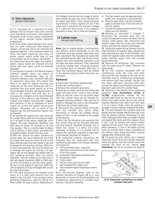
16 To break the joint, obtain two L-shaped<br />
metal bars which fit into the cylinder head bolt<br />
holes <strong>and</strong> gently rock the cylinder head free<br />
towards the front of the vehicle (see<br />
illustration). Do not try to swivel the head on<br />
13.16 Using two cranked bars to break<br />
cylinder head joint<br />
2A