

Rover 214 & 414 Service and Repair Manual - Rover club
Rover 214 & 414 Service and Repair Manual - Rover club
Rover 214 & 414 Service and Repair Manual - Rover club

Create successful ePaper yourself
Turn your PDF publications into a flip-book with our unique Google optimized e-Paper software.
5C•6 Starting <strong>and</strong> charging systems<br />
11.2 Undo retaining nuts <strong>and</strong> remove<br />
support bracket from starter motor<br />
11 Starter motor -<br />
brush <strong>and</strong> solenoid renewal 2<br />
1 Remove the starter motor.<br />
Brushes<br />
Removal<br />
2 Undo the two nuts securing the support<br />
bracket to the rear of the starter motor <strong>and</strong><br />
remove the bracket (see illustration).<br />
3 Undo the two screws <strong>and</strong> remove the small<br />
cover <strong>and</strong> gasket from the centre of the<br />
starter motor end cover (see illustration).<br />
Prise out the C-clip <strong>and</strong> withdraw any<br />
thrustwashers fitted to the armature end.<br />
4 Noting the alignment marks between the<br />
11.4a Note alignment marks between yoke<br />
<strong>and</strong> grommet . . .<br />
11.6b . . . remove brush spring caps <strong>and</strong><br />
springs . . .<br />
11.3 Remove cover to gain access to<br />
armature C-clip<br />
end cover or grommet <strong>and</strong> the yoke, unscrew<br />
the two through-bolts <strong>and</strong> withdraw the end<br />
cover (see illustrations).<br />
5 Carefully prise off the negative (field coil)<br />
brush retaining caps from the brush holder<br />
assembly then remove the springs <strong>and</strong> slide<br />
the brushes out of the holder.<br />
6 Remove the nut <strong>and</strong> spring washer<br />
securing the positive brush lead to the<br />
solenoid terminal <strong>and</strong> slide the brush holder<br />
assembly off the end of the commutator.<br />
Withdraw the plastic insulating plate then<br />
remove the positive brush retaining caps <strong>and</strong><br />
springs <strong>and</strong> remove the positive brushes from<br />
the holder (see illustrations).<br />
Inspection<br />
7 In most cases, the brushes will have wear<br />
limit marks in the form of a groove etched<br />
11.4b . . . then remove through-bolts <strong>and</strong><br />
withdraw end cover<br />
11.6c . . . <strong>and</strong> remove positive brush<br />
assembly from motor<br />
1689 <strong>Rover</strong> <strong>214</strong> & <strong>414</strong> Updated Version 09/97<br />
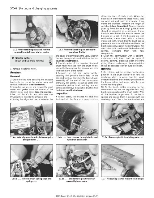
along one face of each brush. When the<br />
brushes are worn down to these marks, they<br />
are worn out <strong>and</strong> must be renewed. If no<br />
marks are provided, measure the length of<br />
each brush (see illustration). No dimension is<br />
given by <strong>Rover</strong> but as a rough guide 3.5 mm<br />
should be regarded as a minimum. If any<br />
brush is worn below this amount, renew the<br />
brushes as a set. If the brushes are still<br />
serviceable, clean them with a solventmoistened<br />
cloth. Check that the brush spring<br />
pressure is equal for all brushes <strong>and</strong> holds the<br />
brushes securely against the commutator. If in<br />
doubt about the condition of the brushes <strong>and</strong><br />
springs, compare them with new<br />
components.<br />
8 Clean the commutator with a solventmoistened<br />
cloth, then check for signs of<br />
scoring, burning, excessive wear or severe<br />
pitting. If worn or damaged, the commutator<br />
should be attended to by an auto-electrician.<br />
Refitting<br />
9 On refitting, slot the positive brushes into<br />
position in the brush holder then refit the<br />
insulating plate, ensuring that the small<br />
threaded brackets are correctly positioned on<br />
the brush holder <strong>and</strong> locate with the pins<br />
on the insulating plate.<br />
10 Fit the brush holder assembly to the<br />
commutator <strong>and</strong> slot the negative (field coil)<br />
brushes into position in the brush holder. With<br />
all the brushes in position, fit the brush<br />
springs <strong>and</strong> secure them in position with the<br />
retaining caps. Check that the brushes are<br />
11.6a Remove plastic insulating plate . . .<br />
11.7 Measuring starter motor brush length