

Rover 214 & 414 Service and Repair Manual - Rover club
Rover 214 & 414 Service and Repair Manual - Rover club
Rover 214 & 414 Service and Repair Manual - Rover club

Create successful ePaper yourself
Turn your PDF publications into a flip-book with our unique Google optimized e-Paper software.
2B•10 Engine removal <strong>and</strong> general overhaul procedures<br />
12.2 Renew liner O-rings<br />
rings <strong>and</strong> to the liner surface on each side of<br />
the rings (see illustration).<br />
3 If the original liners are being refitted, use<br />
the marks made on removal to ensure that<br />
each is refitted the same way round into its<br />
original bore. Insert each liner into the cylinder<br />
block/crankcase, taking great care not to<br />
displace or damage the sealing rings, <strong>and</strong><br />
press it home as far as possible by h<strong>and</strong>.<br />
Using a hammer <strong>and</strong> a block of wood, tap<br />
each liner lightly but fully onto its locating<br />
shoulder (see illustration). Wipe clean, then<br />
lightly oil all exposed liner surfaces to prevent<br />
rusting.<br />
13 Piston/connecting rod<br />
assembly - inspection 3<br />
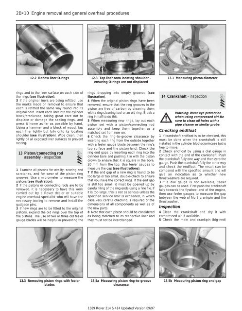
1 Examine all pistons for ovality, scoring <strong>and</strong><br />
scratches, <strong>and</strong> for wear of the piston ring<br />
grooves. Use a micrometer to measure the<br />
pistons (see illustration).<br />
2 If the pistons or connecting rods are to be<br />
renewed, it is necessary to have this work<br />
carried out by a <strong>Rover</strong> dealer or suitable<br />
engine overhaul specialist who will have the<br />
necessary tooling to remove <strong>and</strong> install the<br />
gudgeon pins.<br />
3 If new rings are to be fitted to the original<br />
pistons, exp<strong>and</strong> the old rings over the top of<br />
the pistons. The use of two or three old feeler<br />
gauge blades will be helpful in preventing the<br />
13.3 Removing piston rings with feeler<br />
blades<br />
12.3 Tap liner onto locating shoulder -<br />
ensuring O-rings are not displaced<br />
rings dropping into empty grooves (see<br />
illustration).<br />
4 When the original piston rings have been<br />
removed, ensure that the ring grooves in the<br />
piston are free of carbon by cleaning them<br />
with a ring cleaning tool or an old ring. Break a<br />
ring in half to do this.<br />
5 When measuring new rings, lay out each<br />
piston set with a piston/connecting rod<br />
assembly <strong>and</strong> keep them together as a<br />
matched set from now on.<br />
6 Check the ring-to-groove clearance by<br />
inserting each ring from the outside together<br />
with a feeler gauge blade between the ring’s<br />
top surface <strong>and</strong> the piston l<strong>and</strong>. Check the<br />
ring end gaps by inserting each ring into the<br />
cylinder bore <strong>and</strong> pushing it in with the piston<br />
crown to ensure that it is square in the bore,<br />
20 mm from the top. Use feeler gauges to<br />
measure the gap (see illustrations).<br />
7 If the end gap of a new ring is found to be<br />
too large or too small, double-check to ensure<br />
that you have the correct rings. If the end gap<br />
is still too small, it must be opened up by<br />
careful filing of the ring ends using a fine file. If<br />
it is too large, this is not as serious unless the<br />
specified service limit is exceeded, in which<br />
case very careful checking is required of the<br />
dimensions of all components as well as of<br />
the new parts.<br />
8 Note that each piston should be considered<br />
as being matched to its respective liner <strong>and</strong><br />
they must not be interchanged.<br />
13.5a Measuring piston ring-to-groove<br />
clearance<br />
1689 <strong>Rover</strong> <strong>214</strong> & <strong>414</strong> Updated Version 09/97<br />
13.1 Measuring piston diameter<br />
14 Crankshaft - inspection<br />
3<br />
Warning: Wear eye protection<br />
when using compressed air! Be<br />
sure to clean oil holes with a<br />
pipe cleaner or similar probe.<br />
Checking endfloat<br />
1 If crankshaft endfloat is to be checked, this<br />
must be done when the crankshaft is still<br />
installed in the cylinder block/crankcase but is<br />
free to move.<br />
2 Check endfloat by using a dial gauge in<br />
contact with the end of the crankshaft. Push<br />
the crankshaft fully one way <strong>and</strong> then zero the<br />
gauge. Push the crankshaft fully the other way<br />
<strong>and</strong> check the endfloat. The result can be<br />
compared with the specified amount <strong>and</strong> will<br />
give an indication as to whether new<br />
thrustwashers are required.<br />
3 If a dial gauge is not available, feeler<br />
gauges can be used. First push the crankshaft<br />
fully towards the flywheel end of the engine,<br />
then use feeler gauges to measure the gap<br />
between the web of No 3 crankpin <strong>and</strong> the<br />
thrustwasher.<br />
Inspection<br />
4 Clean the crankshaft <strong>and</strong> dry it with<br />
compressed air, if available.<br />
5 Check the main <strong>and</strong> crankpin (big-end)<br />
13.5b Measuring piston ring end gap