

Rover 214 & 414 Service and Repair Manual - Rover club
Rover 214 & 414 Service and Repair Manual - Rover club
Rover 214 & 414 Service and Repair Manual - Rover club

You also want an ePaper? Increase the reach of your titles
YUMPU automatically turns print PDFs into web optimized ePapers that Google loves.
2A•20 Engine in-car repair procedures<br />
15.4 Alternator adjuster link nut (A) wiring<br />
guide screws (B) oil pump bolts (C) <strong>and</strong><br />
special oil pump bolt (D)<br />
area so that it cannot be contaminated with<br />
oil.<br />
2 Drain the engine oil, then clean <strong>and</strong> refit the<br />
engine oil drain plug, tightening it to the<br />
specified torque wrench setting. If the engine<br />
is nearing its service interval when the oil <strong>and</strong><br />
filter are due for renewal, it is recommended<br />
that the filter is also removed <strong>and</strong> a new one<br />
fitted. After reassembly, the engine can then<br />
be replenished with fresh engine oil.<br />
3 Where necessary, unscrew the alternator<br />
adjuster link retaining nut <strong>and</strong> unbolt the<br />
engine wiring harness guide retaining screws,<br />
then move the link <strong>and</strong> guide clear of the oil<br />
pump.<br />
4 Unscrew the oil pump retaining bolts,<br />
noting the fitted position of the special bolt,<br />
<strong>and</strong> withdraw the oil pump (see illustration).<br />
Recover the pump gasket <strong>and</strong> discard it, then<br />
carefully lever the crankshaft right-h<strong>and</strong> oil<br />
seal out of the oil pump. The oil seal should be<br />
renewed whenever it is disturbed.<br />
Refitting<br />
5 Thoroughly clean the mating faces of the oil<br />
pump <strong>and</strong> cylinder block/crankcase. Use<br />
grease to stick a new gasket in place.<br />
6 Prime the pump before installation by<br />
injecting clean engine oil into it <strong>and</strong> turning it<br />
by h<strong>and</strong>.<br />
7 Offer up the pump, ensuring that its inner<br />
16.4 Unscrewing oil pressure relief valve<br />
threaded plug<br />
15.8 Oil pump bolt tightening sequence<br />
gear engages fully on the crankshaft flats,<br />
then push the pump fully into position.<br />
8 Refit the pump retaining bolts, ensuring that<br />
the special bolt is refitted to its original<br />
position. Tighten the retaining bolts to the<br />
specified torque setting in the order shown<br />
(see illustration).<br />
9 If removed, refit the alternator adjuster link<br />
<strong>and</strong> the engine wiring harness guide, then<br />
tighten securely the retaining nut <strong>and</strong> screws.<br />
10 Fit a new crankshaft right-h<strong>and</strong> oil seal.<br />
11 Remove all traces of surplus oil then refit<br />
the crankshaft sprocket.<br />
12 Replenish the engine oil.<br />
16 Oil pump - dismantling,<br />
inspection <strong>and</strong> reassembly 4<br />
Note: If oil pump wear is suspected, check the<br />
cost <strong>and</strong> availability of new parts (only<br />
available in the form of repair kit LQX 10001)<br />
against the cost of a new pump. Examine the<br />
pump as described in this Section <strong>and</strong> then<br />
decide whether renewal or repair is the best<br />
course of action.<br />
Dismantling<br />
1 Remove the oil pump.<br />
2 Unscrew the Torx screws (size T25) <strong>and</strong><br />
remove the pump cover plate. Discard the<br />
sealing ring.<br />
3 Note the identification marks on the outer<br />
rotor then remove both the rotors from the<br />
body.<br />
16.5 Oil pressure relief valve assembly<br />
1 Threaded plug<br />
2 Valve spring <strong>and</strong> plunger<br />
1689 <strong>Rover</strong> <strong>214</strong> & <strong>414</strong> Updated Version 09/97<br />
4 The oil pressure relief valve can be<br />
dismantled, if required, without disturbing the<br />
pump. If this is to be done with the pump in<br />
position <strong>and</strong> the engine still installed in the<br />
vehicle, it will first be necessary to jack up the<br />
front of the vehicle <strong>and</strong> remove the right-h<strong>and</strong><br />
roadwheel to gain access to the valve (see<br />
illustration).<br />
5 To dismantle the valve, unscrew the<br />
threaded plug <strong>and</strong> recover the valve spring<br />
<strong>and</strong> plunger (see illustration). Discard the<br />
plug sealing washer.<br />
Inspection<br />
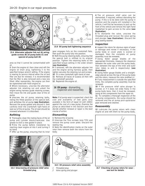
6 Inspect the rotors for obvious signs of wear<br />
or damage <strong>and</strong> renew if necessary. If the<br />
pump body or cover plate is scored or<br />
damaged, then the complete oil pump<br />
assembly must be renewed.<br />
7 Using feeler gauge blades of the<br />
appropriate thickness, measure the clearance<br />
between the outer rotor <strong>and</strong> the pump body,<br />
then between the tips of the inner <strong>and</strong> outer<br />
rotor lobes (a <strong>and</strong> b respectively) (see<br />
illustration).<br />
8 Using feeler gauge blades <strong>and</strong> a straightedge<br />
placed across the top of the pump body<br />
<strong>and</strong> the rotors, measure the rotor endfloat (c).<br />
9 If any measurement is outside the specified<br />
limits, the complete pump assembly must be<br />
renewed.<br />
10 If the pressure relief valve plunger is<br />
scored, or if it does not slide freely in the<br />
pump body bore, then it must be renewed,<br />
using all the components from the repair kit.<br />
11 To complete a thorough inspection of the<br />
oil pump components, the sump should be<br />
removed <strong>and</strong> the oil pump pick-up/strainer<br />
pipe removed <strong>and</strong> cleaned.<br />
Reassembly<br />
12 Lubricate the pump rotors with clean<br />
engine oil <strong>and</strong> refit them to the pump body,<br />
16.7 Checking oil pump rotors for wear -<br />
see text for details