

Rover 214 & 414 Service and Repair Manual - Rover club
Rover 214 & 414 Service and Repair Manual - Rover club
Rover 214 & 414 Service and Repair Manual - Rover club

You also want an ePaper? Increase the reach of your titles
YUMPU automatically turns print PDFs into web optimized ePapers that Google loves.
8.6 Crankshaft pulley mark aligned with<br />
timing belt lower cover mark at 90° BTDC<br />
clear of the timing belt covers. Take great care<br />
not to place any undue strain on hoses <strong>and</strong><br />
mop up any spilt fluid immediately.<br />
3 Remove the timing belt upper right-h<strong>and</strong><br />
(outer) cover.<br />
4 Firmly apply the h<strong>and</strong>brake then jack up the<br />
front of the vehicle <strong>and</strong> support it on axle<br />
st<strong>and</strong>s. Remove the right-h<strong>and</strong> roadwheel<br />
5 From underneath the front of the vehicle,<br />
slacken <strong>and</strong> remove the three bolts securing<br />
the bumper flange to the body. Remove the<br />
seven bolts securing the front undercover<br />
panel to the body <strong>and</strong> remove the panel to<br />
gain access to the crankshaft pulley bolt.<br />
6 Using a suitable spanner or socket on the<br />
crankshaft pulley bolt, rotate the crankshaft in<br />
a clockwise direction until the long whitepainted<br />
mark on the crankshaft pulley’s<br />
outboard (right-h<strong>and</strong>) face is aligned with the<br />
single, separate mark on the timing belt lower<br />
cover so that the crankshaft is in the 90°<br />
BTDC position (see Chapter 1 for details of<br />
the pulley/cover marks) (see illustration).<br />
7 Check that the camshaft sprocket mark(s)<br />
align as described in paragraph 15, showing<br />
that Nos 1 <strong>and</strong> 4 cylinders are at 90° BTDC<br />
so that there is no risk of the valves contacting<br />
the pistons during dismantling <strong>and</strong><br />
reassembly. If the camshaft sprocket mark(s)<br />
are 180° out, rotate the crankshaft through<br />
one complete turn (360°) to align the marks as<br />
described (see illustration).<br />
8 On K16 engines, use the tool described in<br />
Section 9 to lock up the camshaft sprockets<br />
8.12 Timing belt tensioner pulley bolt (A)<br />
<strong>and</strong> tensioner backplate clamp bolt (B)<br />
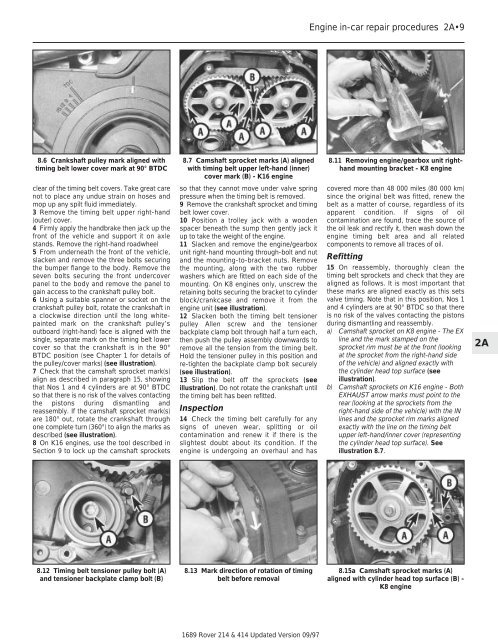
8.7 Camshaft sprocket marks (A) aligned<br />
with timing belt upper left-h<strong>and</strong> (inner)<br />
cover mark (B) - K16 engine<br />
so that they cannot move under valve spring<br />
pressure when the timing belt is removed.<br />
9 Remove the crankshaft sprocket <strong>and</strong> timing<br />
belt lower cover.<br />
10 Position a trolley jack with a wooden<br />
spacer beneath the sump then gently jack it<br />
up to take the weight of the engine.<br />
11 Slacken <strong>and</strong> remove the engine/gearbox<br />
unit right-h<strong>and</strong> mounting through-bolt <strong>and</strong> nut<br />
<strong>and</strong> the mounting-to-bracket nuts. Remove<br />
the mounting, along with the two rubber<br />
washers which are fitted on each side of the<br />
mounting. On K8 engines only, unscrew the<br />
retaining bolts securing the bracket to cylinder<br />
block/crankcase <strong>and</strong> remove it from the<br />
engine unit (see illustration).<br />
12 Slacken both the timing belt tensioner<br />
pulley Allen screw <strong>and</strong> the tensioner<br />
backplate clamp bolt through half a turn each,<br />
then push the pulley assembly downwards to<br />
remove all the tension from the timing belt.<br />
Hold the tensioner pulley in this position <strong>and</strong><br />
re-tighten the backplate clamp bolt securely<br />
(see illustration).<br />
13 Slip the belt off the sprockets (see<br />
illustration). Do not rotate the crankshaft until<br />
the timing belt has been refitted.<br />
Inspection<br />
14 Check the timing belt carefully for any<br />
signs of uneven wear, splitting or oil<br />
contamination <strong>and</strong> renew it if there is the<br />
slightest doubt about its condition. If the<br />
engine is undergoing an overhaul <strong>and</strong> has<br />
8.13 Mark direction of rotation of timing<br />
belt before removal<br />
1689 <strong>Rover</strong> <strong>214</strong> & <strong>414</strong> Updated Version 09/97<br />
Engine in-car repair procedures 2A•9<br />
8.11 Removing engine/gearbox unit righth<strong>and</strong><br />
mounting bracket - K8 engine<br />
covered more than 48 000 miles (80 000 km)<br />
since the original belt was fitted, renew the<br />
belt as a matter of course, regardless of its<br />
apparent condition. If signs of oil<br />
contamination are found, trace the source of<br />
the oil leak <strong>and</strong> rectify it, then wash down the<br />
engine timing belt area <strong>and</strong> all related<br />
components to remove all traces of oil.<br />
Refitting<br />
15 On reassembly, thoroughly clean the<br />
timing belt sprockets <strong>and</strong> check that they are<br />
aligned as follows. It is most important that<br />
these marks are aligned exactly as this sets<br />
valve timing. Note that in this position, Nos 1<br />
<strong>and</strong> 4 cylinders are at 90° BTDC so that there<br />
is no risk of the valves contacting the pistons<br />
during dismantling <strong>and</strong> reassembly.<br />
a) Camshaft sprocket on K8 engine - The EX<br />
line <strong>and</strong> the mark stamped on the<br />
sprocket rim must be at the front (looking<br />
at the sprocket from the right-h<strong>and</strong> side<br />
of the vehicle) <strong>and</strong> aligned exactly with<br />
the cylinder head top surface (see<br />
illustration).<br />
b) Camshaft sprockets on K16 engine - Both<br />
EXHAUST arrow marks must point to the<br />
rear (looking at the sprockets from the<br />
right-h<strong>and</strong> side of the vehicle) with the IN<br />
lines <strong>and</strong> the sprocket rim marks aligned<br />
exactly with the line on the timing belt<br />
upper left-h<strong>and</strong>/inner cover (representing<br />
the cylinder head top surface). See<br />
illustration 8.7.<br />
8.15a Camshaft sprocket marks (A)<br />
aligned with cylinder head top surface (B) -<br />
K8 engine<br />
2A