

Rover 214 & 414 Service and Repair Manual - Rover club
Rover 214 & 414 Service and Repair Manual - Rover club
Rover 214 & 414 Service and Repair Manual - Rover club

Create successful ePaper yourself
Turn your PDF publications into a flip-book with our unique Google optimized e-Paper software.
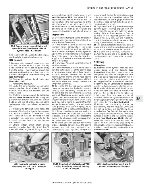
11.9 Secure partly-removed timing belt<br />
upper left-h<strong>and</strong> (inner) cover clear of<br />
cylinder head - K16 engine<br />
time to refill with oil on restarting the engine,<br />
resulting in incorrect valve clearances.<br />
K16 engines<br />
9 Remove both camshaft sprockets, then<br />
unscrew the inner cover’s upper retaining<br />
bolts so that the cover can be pulled away<br />
from the cylinder head just far enough for<br />
adequate working clearance. Take care not to<br />
distort or damage the cover or the timing belt<br />
(see illustration).<br />
10 Remove the cylinder head cover (see<br />
illustration 11.0b).<br />
11 Remove the distributor.<br />
12 Unclip the air temperature control valve<br />
vacuum pipe from the air intake duct support<br />
bracket, then unbolt the bracket from the<br />
cylinder head.<br />
13 Working in the reverse of the tightening<br />
sequence (see illustration 11.36), evenly <strong>and</strong><br />
progressively slacken the camshaft carrier<br />
bolts by one turn at a time. Once all valve<br />
spring pressure has been relieved, remove the<br />
bolts.<br />
14 Withdraw the camshaft carrier, noting the<br />
presence of the locating dowels, then remove<br />
the camshafts <strong>and</strong> slide off the oil seals. The<br />
inlet camshaft can be identified by the<br />
distributor rotor arm drive spindle (or its<br />
location), therefore there is no need to mark<br />
the camshafts.<br />
15 Obtain sixteen small, clean plastic<br />
containers, number them 1 to 16, <strong>and</strong> then fill<br />
them with clean engine oil. Using a rubber<br />
11.26 Lubricate hydraulic tappets<br />
thoroughly <strong>and</strong> refit correct way up -<br />
K8 engine<br />
sucker, withdraw each hydraulic tappet in turn<br />
(see illustration 11.8), <strong>and</strong> place it in its<br />
respective container, to prevent oil loss. Do<br />
not interchange the hydraulic tappets or the<br />
rate of wear will be much increased <strong>and</strong> do<br />
not allow them to lose oil or they will take a<br />
long time to refill with oil on restarting the<br />
engine, resulting in incorrect valve clearances.<br />
Inspection<br />
16 Check each hydraulic tappet for signs of<br />
obvious wear (scoring, pitting, etc) <strong>and</strong> for<br />
ovality. Renew if necessary.<br />
17 If the engine’s valve clearances have<br />
sounded noisy, particularly if the noise<br />
persists after initial start-up from cold, then<br />
there is reason to suspect a faulty hydraulic<br />
tappet. Only a good mechanic experienced in<br />
these engines can tell whether the noise level<br />
is typical, or if renewal is warranted of one or<br />
more of the tappets.<br />
18 If any tappet’s operation is faulty, then it<br />
must be renewed.<br />
19 Carefully remove all traces of old sealant<br />
from the mating surfaces of the bearing caps<br />
or camshaft carrier <strong>and</strong> cylinder head by using<br />
a plastic scraper. Examine the camshaft<br />
bearing journals <strong>and</strong> the cylinder head bearing<br />
surfaces for signs of obvious wear or pitting. If<br />
any such signs are evident, renew the<br />
component concerned.<br />
20 To check the bearing journal running<br />
clearance, remove the hydraulic tappets,<br />
carefully clean the bearing surfaces <strong>and</strong> refit<br />
the camshaft(s) <strong>and</strong> carrier/bearing caps with a<br />
str<strong>and</strong> of Plastigauge across each journal.<br />
Tighten the carrier/bearing cap bolts to the<br />
specified torque wrench setting whilst taking<br />
great care not to rotate the camshaft(s), then<br />
remove the carrier/bearing caps <strong>and</strong> use the<br />
scale provided with the Plastigauge kit to<br />
measure the width of each compressed str<strong>and</strong>.<br />
21 If the running clearance of any bearing is<br />
found to be worn to the specified service limit<br />
or beyond, fit a new camshaft <strong>and</strong> repeat the<br />
check. If the clearance is still excessive, then<br />
the cylinder head must be renewed.<br />
22 To check camshaft endfloat, remove the<br />
hydraulic tappets, carefully clean the bearing<br />
surfaces <strong>and</strong> refit the camshaft(s) <strong>and</strong><br />
carrier/bearing caps. Tighten to the specified<br />
11.27 Camshaft roll pin location at TDC<br />
position (for refitting camshaft bearing<br />
caps) - K8 engine<br />
1689 <strong>Rover</strong> <strong>214</strong> & <strong>414</strong> Updated Version 09/97<br />
Engine in-car repair procedures 2A•15<br />
torque wrench setting the carrier/bearing cap<br />
bolts, then measure the endfloat using a Dial<br />
Test Indicator (DTI) or dial gauge mounted on<br />
the cylinder head so that its tip bears on the<br />
camshaft right-h<strong>and</strong> end.<br />
23 Tap the camshaft fully towards the gauge,<br />
zero the gauge, then tap the camshaft fully<br />
away from the gauge <strong>and</strong> note the gauge<br />
reading. If the endfloat measured is found to<br />
be worn to the specified service limit or<br />
beyond, fit a new camshaft <strong>and</strong> repeat the<br />
check. If the clearance is still excessive, then<br />
the cylinder head must be renewed.<br />
24 The camshaft itself should show no signs of<br />
marks, pitting or scoring on the lobe surfaces. If<br />
such marks are evident, renew the camshaft.<br />
25 If a camshaft is renewed, extract the roll<br />
pin from the old one <strong>and</strong> fit the pin to the new<br />
camshaft with its split towards the camshaft’s<br />
centre.<br />
Refitting<br />
K8 engines<br />
26 Liberally oil the cylinder head hydraulic<br />
tappet bores <strong>and</strong> the tappets (see<br />
illustration). Note that if new tappets are<br />
being fitted, they must be charged with clean<br />
engine oil before installation. Carefully refit the<br />
tappets to the cylinder head, ensuring that<br />
each tappet is refitted to its original bore <strong>and</strong> is<br />
the correct way up. Some care will be required<br />
to enter the tappets squarely into their bores.<br />
27 Liberally oil the camshaft bearings <strong>and</strong><br />
lobes then refit the camshaft. Position the<br />
shaft so that its No 1 cylinder lobes are<br />
pointing away from their valves <strong>and</strong> the roll<br />
pin in the camshaft’s right-h<strong>and</strong> end is in the<br />
4 o’clock position when viewed from the righth<strong>and</strong><br />
end of the engine (see illustration).<br />
28 Ensure that the locating dowels are<br />
pressed firmly into their recesses. Check that<br />
the mating surfaces are completely clean,<br />
unmarked <strong>and</strong> free from oil, then apply a thin<br />
bead of special <strong>Rover</strong> sealant to the mating<br />
surfaces of the front <strong>and</strong> rear bearing caps as<br />
shown (see illustration 11.29). Carefully<br />
follow the instructions supplied with the<br />
sealant kit. Refit the bearing caps, using the<br />
notes made on removal, to ensure that each is<br />
installed correctly <strong>and</strong> in its original location<br />
(see illustration).<br />
11.28 Apply sealant (arrowed) <strong>and</strong> fit<br />
camshaft bearing caps - K8 engine<br />
2A