

Rover 214 & 414 Service and Repair Manual - Rover club
Rover 214 & 414 Service and Repair Manual - Rover club
Rover 214 & 414 Service and Repair Manual - Rover club

You also want an ePaper? Increase the reach of your titles
YUMPU automatically turns print PDFs into web optimized ePapers that Google loves.
tightens each bolt through half a turn so that<br />
the marks face away from each other <strong>and</strong> the<br />
third stage tightens them through another<br />
half-turn so that all the bolt-head marks will<br />
then align again with their cylinder head<br />
counterparts. If any bolt is overtightened past<br />
its mark, slacken it through 90°, then retighten<br />
until the marks align (see illustration).<br />
30 Refit <strong>and</strong> tighten the inlet manifold<br />
support stay bolts, then secure the engine<br />
wiring harness using the clips provided.<br />
31 On K16 engines equipped with air<br />
conditioning, refit the alternator mounting<br />
bolts <strong>and</strong> tighten them to the specified torque<br />
setting. Refit the compressor <strong>and</strong> alternator<br />
heatshields, tightening their retaining bolts<br />
<strong>and</strong> nuts securely.<br />
32 Connect all disturbed coolant hoses,<br />
securing them in position with their retaining<br />
clips. Reconnect the coolant temperature<br />
sensor wiring.<br />
33 Working as described in Chapter 4,<br />
connect or refit all disturbed wiring, hoses <strong>and</strong><br />
control cable(s) to the inlet manifold <strong>and</strong> fuel<br />
system components, then adjust the choke<br />
<strong>and</strong> or accelerator cable(s).<br />
34 Reconnect the exhaust system front pipe<br />
to the manifold <strong>and</strong> (if applicable) reconnect<br />
the lambda sensor wiring.<br />
35 Refit the cylinder head cover, inner timing<br />
cover retaining bolts <strong>and</strong> camshaft<br />
sprocket(s).<br />
36 Refit the spark plugs <strong>and</strong> distributor cap<br />
then reconnect the battery negative lead.<br />
37 Refill the cooling system.<br />
14 Sump -<br />
removal <strong>and</strong> refitting 2<br />
Note: It is essential that new bolts of the<br />
Patchlok type are used when refitting the<br />
sump.<br />
Removal<br />
1 Disconnect the battery negative lead.<br />
2 Drain the engine oil then clean <strong>and</strong> refit the<br />
engine oil drain plug, tightening it to the<br />
specified torque wrench setting. If the engine<br />
is nearing its service interval when the oil <strong>and</strong><br />
filter are due for renewal, it is recommended<br />
that the filter is also removed <strong>and</strong> a new one<br />
fitted. After reassembly, the engine can then<br />
be replenished with fresh engine oil.<br />
3 Apply the h<strong>and</strong>brake, then jack up the front<br />
of the vehicle <strong>and</strong> support it on axle st<strong>and</strong>s.<br />
Remove the right-h<strong>and</strong> roadwheel.<br />
4 From underneath the front of the vehicle,<br />
slacken <strong>and</strong> remove the three bolts securing<br />
the bumper flange to the body. Remove the<br />
seven bolts securing the front undercover<br />
panel to the body <strong>and</strong> remove the panel.<br />
5 Working as described in Chapter 4,<br />
disconnect the exhaust system front pipe<br />
from the manifold <strong>and</strong>, where fitted,<br />
disconnect or release the lambda sensor<br />
14.6 Remove flywheel lower cover plate to<br />
reach sump bolts<br />
wiring so that it is not strained by the weight<br />
of the exhaust.<br />
6 Unscrew the three retaining bolts <strong>and</strong><br />
remove the flywheel lower cover plate (see<br />
illustration).<br />
7 Slacken <strong>and</strong> remove the bolts securing the<br />
anti-beaming bracket to the engine <strong>and</strong><br />
transmission <strong>and</strong> remove the bracket.<br />
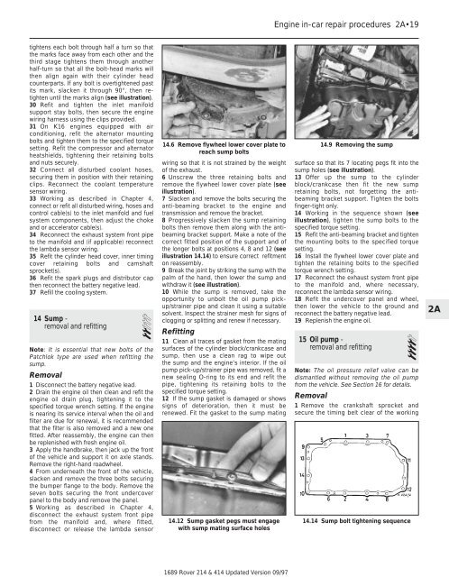
8 Progressively slacken the sump retaining<br />
bolts then remove them along with the antibeaming<br />
bracket support. Make a note of the<br />
correct fitted position of the support <strong>and</strong> of<br />
the longer bolts at positions 4, 8 <strong>and</strong> 12 (see<br />
illustration 14.14) to ensure correct refitment<br />
on reassembly.<br />
9 Break the joint by striking the sump with the<br />
palm of the h<strong>and</strong>, then lower the sump <strong>and</strong><br />
withdraw it (see illustration).<br />
10 While the sump is removed, take the<br />
opportunity to unbolt the oil pump pickup/strainer<br />
pipe <strong>and</strong> clean it using a suitable<br />
solvent. Inspect the strainer mesh for signs of<br />
clogging or splitting <strong>and</strong> renew if necessary.<br />
Refitting<br />
11 Clean all traces of gasket from the mating<br />
surfaces of the cylinder block/crankcase <strong>and</strong><br />
sump, then use a clean rag to wipe out<br />
the sump <strong>and</strong> the engine’s interior. If the oil<br />
pump pick-up/strainer pipe was removed, fit a<br />
new sealing O-ring to its end <strong>and</strong> refit the<br />
pipe, tightening its retaining bolts to the<br />
specified torque setting.<br />
12 If the sump gasket is damaged or shows<br />
signs of deterioration, then it must be<br />
renewed. Fit the gasket to the sump mating<br />
14.12 Sump gasket pegs must engage<br />
with sump mating surface holes<br />
1689 <strong>Rover</strong> <strong>214</strong> & <strong>414</strong> Updated Version 09/97<br />
Engine in-car repair procedures 2A•19<br />
14.9 Removing the sump<br />
surface so that its 7 locating pegs fit into the<br />
sump holes (see illustration).<br />
13 Offer up the sump to the cylinder<br />
block/crankcase then fit the new sump<br />
retaining bolts, not forgetting the antibeaming<br />
bracket support. Tighten the bolts<br />
finger-tight only.<br />
14 Working in the sequence shown (see<br />
illustration), tighten the sump bolts to the<br />
specified torque setting.<br />
15 Refit the anti-beaming bracket <strong>and</strong> tighten<br />
the mounting bolts to the specified torque<br />
setting.<br />
16 Install the flywheel lower cover plate <strong>and</strong><br />
tighten the retaining bolts to the specified<br />
torque wrench setting.<br />
17 Reconnect the exhaust system front pipe<br />
to the manifold <strong>and</strong>, where necessary,<br />
reconnect the lambda sensor wiring.<br />
18 Refit the undercover panel <strong>and</strong> wheel,<br />
then lower the vehicle to the ground <strong>and</strong><br />
reconnect the battery negative lead.<br />
19 Replenish the engine oil.<br />
15 Oil pump -<br />
removal <strong>and</strong> refitting 4<br />
Note: The oil pressure relief valve can be<br />
dismantled without removing the oil pump<br />
from the vehicle. See Section 16 for details.<br />
Removal<br />
1 Remove the crankshaft sprocket <strong>and</strong><br />
secure the timing belt clear of the working<br />
14.14 Sump bolt tightening sequence<br />
2A