

Rover 214 & 414 Service and Repair Manual - Rover club
Rover 214 & 414 Service and Repair Manual - Rover club
Rover 214 & 414 Service and Repair Manual - Rover club

You also want an ePaper? Increase the reach of your titles
YUMPU automatically turns print PDFs into web optimized ePapers that Google loves.
Refitting<br />
9 Refitting is reversal of the removal<br />
procedure noting the following:<br />
a) Ensure that the lug on the base of the<br />
suspension strut correctly engages with<br />
the slot in the swivel hub assembly clamp.<br />
b) Tighten all nuts <strong>and</strong> bolts to the specified<br />
torque.<br />
c) Where necessary, refit the brake disc<br />
<strong>and</strong>/or ABS wheel sensor as described in<br />
Chapter 9.<br />
d) Use new split pins to secure the track rod<br />
<strong>and</strong> lower suspension arm balljoint<br />
retaining nuts in position.<br />
e) When fitting the new driveshaft retaining<br />
nut, tighten it to the specified torque then<br />
stake it firmly into the groove in the<br />
constant velocity joint by using a suitable<br />
punch.<br />
3 Front hub bearings -<br />
removal <strong>and</strong> refitting 4<br />
Note: The front hub bearing is a sealed, preadjusted<br />
<strong>and</strong> pre-lubricated, double-row roller<br />
type, <strong>and</strong> is intended to last the vehicle’s<br />
entire service life without maintenance or<br />
attention. Do not attempt to remove the<br />
bearing unless absolutely necessary, as it will<br />
probably be damaged during the removal<br />
operation. Never overtighten the driveshaft nut<br />
beyond the specified torque wrench setting in<br />
an attempt to ‘adjust’ the bearing.<br />
Note: A press will be required to dismantle<br />
<strong>and</strong> rebuild the hub assembly. If such a tool is<br />
not available, a large bench vice <strong>and</strong> suitable<br />
spacers (such as large sockets) will serve as<br />
an adequate substitute. The service tool<br />
numbers for the special <strong>Rover</strong> m<strong>and</strong>rels are<br />
given in the accompanying illustrations. The<br />
bearing’s inner races are an interference fit on<br />
the hub. If the outboard inner race remains on<br />
the hub when it is pressed out of the hub<br />
carrier, a proprietary knife-edged bearing<br />
puller will be required to remove it.<br />
Removal<br />
1 Remove the swivel hub assembly, then<br />
undo the brake disc shield retaining screws<br />
<strong>and</strong> remove the shield from the hub.<br />
2 Press the hub out of the swivel hub using a<br />
tubular spacer (see illustration). If the<br />
bearing’s outboard inner race remains on the<br />
hub, remove it using a suitable bearing puller.<br />
3 Extract both circlips from the swivel hub<br />
<strong>and</strong> discard them as they should be renewed<br />
whenever disturbed.<br />
4 Press the bearing out of the swivel hub by<br />
using a suitable tubular spacer (see<br />
illustration).<br />
5 Thoroughly clean the hub <strong>and</strong> swivel hub,<br />
removing all traces of dirt <strong>and</strong> grease. Polish<br />
away any burrs or raised edges which might<br />
hinder reassembly. Check both for cracks or<br />
any other signs of wear or damage <strong>and</strong> renew<br />
3.2 Pressing out hub from swivel hub<br />
the hub if necessary. The bearing <strong>and</strong> its<br />
circlips must be renewed whenever they are<br />
disturbed. A replacement bearing kit is<br />
available from <strong>Rover</strong> dealers which consists of<br />
the bearing <strong>and</strong> both circlips.<br />
6 Check the condition of the roadwheel studs<br />
in the hub flange. If any are sheared off,<br />
stretched or have damaged threads, they can<br />
be pressed out of the hub providing that its<br />
flange is fully supported. On refitting, support<br />
the hub flange <strong>and</strong> press in the new stud until<br />
it seats fully.<br />
Refitting<br />
7 On reassembly, check (if possible) that the<br />
new bearing is packed with grease <strong>and</strong> fit the<br />
new circlip to the swivel hub outboard groove.<br />
Apply a light film of oil to the bearing inner <strong>and</strong><br />
outer races <strong>and</strong> to the matching surfaces in<br />
the hub <strong>and</strong> swivel hub to aid fitting of the<br />
bearing.<br />
8 Support the swivel hub outboard face <strong>and</strong>,<br />
using a suitable tubular spacer which bears<br />
only on the bearing’s outer race, press in the<br />
new bearing until it seats against the circlip<br />
(see illustration). Secure the bearing in<br />
position by fitting the second new circlip to<br />
the swivel hub’s inboard groove.<br />
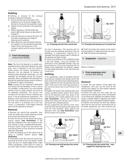
9 Fully supporting the bearing inner race,<br />
press the hub into the bearing <strong>and</strong> swivel hub<br />
until the hub shoulder seats against the<br />
bearing’s inner race (see illustration). Wipe<br />
off any surplus oil or grease.<br />
3.8 Pressing new hub bearing into swivel<br />
hub<br />
1689 <strong>Rover</strong> <strong>214</strong> & <strong>414</strong> Updated Version 09/97<br />
Suspension <strong>and</strong> steering 10•5<br />
3.4 Pressing hub bearing out of swivel hub<br />
10 Refit the brake disc shield to the swivel<br />
hub <strong>and</strong> tighten its retaining screws securely.<br />
11 Refit the swivel hub assembly.<br />
4 Suspension - inspection<br />
Refer to Chapter 1.<br />
5 Front suspension strut -<br />
removal <strong>and</strong> refitting 3<br />
Removal<br />
1 Chock the rear wheels, firmly apply the<br />
h<strong>and</strong>brake, then jack up the front of the<br />
vehicle <strong>and</strong> support on axle st<strong>and</strong>s. Remove<br />
the appropriate roadwheel.<br />
2 Extract the split pin <strong>and</strong> undo the nut<br />
securing the steering gear track rod balljoint<br />
to the swivel hub. Release the balljoint shank,<br />
using a suitable balljoint separator tool whilst<br />
taking care not to damage the balljoint gaiter.<br />
3 Slacken <strong>and</strong> remove the bolt <strong>and</strong> washer<br />
securing the anti-roll bar connecting link to<br />
the lower suspension arm, then undo the two<br />
3.9 Pressing hub into swivel hub - note<br />
support for bearing inner race<br />
10