

Rover 214 & 414 Service and Repair Manual - Rover club
Rover 214 & 414 Service and Repair Manual - Rover club
Rover 214 & 414 Service and Repair Manual - Rover club

Create successful ePaper yourself
Turn your PDF publications into a flip-book with our unique Google optimized e-Paper software.
10•20 Suspension <strong>and</strong> steering<br />
26.4a Power steering oil cooler upper<br />
mounting bolts (arrowed)<br />
4 Undo the three oil cooler mounting bracket<br />
retaining bolts, then manoeuvre the oil cooler<br />
assembly out from between the front bumper<br />
<strong>and</strong> body (see illustrations).<br />
Refitting<br />
5 Refitting is the reverse of the removal<br />
procedure. On completion, bleed the system.<br />
27 Power steering system -<br />
bleeding 2<br />
Warning: Avoid holding the<br />
steering at full lock for long<br />
periods of time. Failure to do so<br />
could lead to overheating, <strong>and</strong><br />
possible damage, of the power steering<br />
pump <strong>and</strong> steering gear.<br />
1 Remove the cap from the power steering<br />
fluid reservoir <strong>and</strong> fill the reservoir with the<br />
specified fluid.<br />
2 Disconnect the distributor wiring to prevent<br />
the engine from starting, then turn the engine<br />
over for approximately 5 seconds to prime the<br />
power steering pump.<br />
3 Reconnect the distributor wiring, then<br />
check the reservoir fluid level is between the<br />
MAX <strong>and</strong> MIN level markings on the side of<br />
the reservoir, topping up if necessary.<br />
4 Start the engine <strong>and</strong> allow it to idle for<br />
approximately 30 seconds with the front wheels<br />
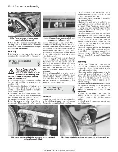
28.4 Using a universal balljoint separator to free track rod<br />
balljoint from swivel hub<br />
26.4b Oil cooler lower mounting bolt can<br />
be accessed via bumper grille<br />
pointing in the straight-ahead position. After 30<br />
seconds, turn the steering onto full lock in one<br />
direction, hold it there for a few seconds, then<br />
turn it onto full lock in the opposite direction <strong>and</strong><br />
hold it there for a few seconds. Return the front<br />
wheels to the straight-ahead position. Repeat<br />
this procedure until air bubbles cease to appear<br />
in the fluid reservoir.<br />
5 If, when turning the steering, an abnormal<br />
noise is heard from the fluid lines, it indicates<br />
that there is still air in the system. Check this<br />
by turning the wheels to the straight-ahead<br />
position <strong>and</strong> switching off the engine. If the<br />
fluid level in the reservoir rises, then air is<br />
present in the system <strong>and</strong> further bleeding is<br />
necessary.<br />
6 Once all traces of air have been removed<br />
from the power steering hydraulic system,<br />
turn the engine off <strong>and</strong> allow the system to<br />
cool. Once cool, check that fluid level is up to<br />
the MAX mark on the power steering fluid<br />
reservoir. Top up if necessary.<br />
28 Track rod balljoint -<br />
removal <strong>and</strong> refitting 5<br />
Removal<br />
1 Apply the h<strong>and</strong>brake, then jack up the front<br />
of the vehicle <strong>and</strong> support it on axle st<strong>and</strong>s.<br />
Remove the appropriate front roadwheel.<br />
1689 <strong>Rover</strong> <strong>214</strong> & <strong>414</strong> Updated Version 09/97<br />
2 If the balljoint is to be re-used, use a<br />
straight-edge <strong>and</strong> a scriber, or similar, to mark<br />
its relationship to the track rod.<br />
3 Holding the balljoint, unscrew its locknut by<br />
one quarter of a turn.<br />
4 Extract the split pin <strong>and</strong> undo the nut<br />
securing the steering gear track rod balljoint<br />
to the swivel hub. Release the balljoint shank<br />
by using a suitable balljoint separator tool<br />
whilst taking care not to damage the balljoint<br />
gaiter (see illustration).<br />
5 Unscrew the balljoint from the track rod,<br />
counting the exact number of turns necessary<br />
to do so. If the locknut is to be removed, mark<br />
its position on the track rod <strong>and</strong> count the<br />
number of turns required to remove it so that<br />
it can be returned exactly to its original<br />
position on reassembly.<br />
6 Carefully clean the balljoint <strong>and</strong> the threads.<br />
Renew the balljoint if its movement is sloppy<br />
or too stiff, if it is excessively worn, or if it is<br />
damaged in any way. Carefully check the stud<br />
taper <strong>and</strong> threads. No grease leakage should<br />
be visible.<br />
Refitting<br />
7 If necessary, screw the locknut onto the<br />
track rod by the number of turns noted on<br />
removal. This should align the locknut with the<br />
mark made on dismantling.<br />
8 Screw the balljoint onto the track rod by the<br />
number of turns noted on removal. This<br />
should bring the balljoint to within a quarter of<br />
a turn from the locknut, with the alignment<br />
marks that were made (if applicable) on<br />
removal lined up.<br />
9 Refit the balljoint shank to the swivel hub<br />
<strong>and</strong> tighten its retaining nut to the specified<br />
torque setting. Use a new split pin to<br />
secure the retaining nut in position (see<br />
illustration).<br />
10 Refit the roadwheel, then lower the<br />
vehicle to the ground <strong>and</strong> tighten the<br />
roadwheel nuts to the specified torque<br />
setting.<br />
11 Check <strong>and</strong>, if necessary, adjust front<br />
wheel alignment.<br />
28.9 Secure balljoint retaining nut in position with new split pin