

Rover 214 & 414 Service and Repair Manual - Rover club
Rover 214 & 414 Service and Repair Manual - Rover club
Rover 214 & 414 Service and Repair Manual - Rover club

Create successful ePaper yourself
Turn your PDF publications into a flip-book with our unique Google optimized e-Paper software.
18.9 Ensure grooved bearing shells<br />
(arrowed) are installed exactly as<br />
described in text - early engine shown<br />
Main bearing running clearance<br />
check<br />
7 Clean the backs of the bearing shells<br />
<strong>and</strong> the bearing locations in both the<br />
cylinder block/crankcase <strong>and</strong> the main<br />
bearing ladder.<br />
8 Press the bearing shells into their locations,<br />
ensuring that the tab on each shell engages in<br />
the notch in the cylinder block/crankcase or<br />
main bearing ladder location. Take care not to<br />
touch any shell bearing surface with your<br />
fingers.<br />
9 Press the bearing shells with the oil grooves<br />
into the upper locations (in the cylinder<br />
block/crankcase). Note the following points<br />
(see illustration):<br />
a) On all engines, grooved bearing shells are<br />
fitted to Nos 2, 3 <strong>and</strong> 4 upper bearing<br />
locations. Note the central locating tabs<br />
of the grooved shells.<br />
b) On early engines, grooved bearing shells<br />
were fitted only to Nos 2 <strong>and</strong> 4 upper<br />
bearing locations at the factory. On<br />
reassembly of one of these units, a<br />
grooved shell must be fitted at No 3<br />
upper bearing location as well, instead of<br />
the plain item originally used. Note,<br />
however, that this will require a grooved<br />
shell with an offset locating tab instead of<br />
the central tab that is used on all other<br />
grooved shells. See your <strong>Rover</strong> dealer for<br />
details.<br />
c) If bearing shells of differing grades are to<br />
be fitted to the same journal, the thicker<br />
shell must always be fitted to the main<br />
bearing ladder location (see paragraph 1).<br />
d) On all engines, if the original main bearing<br />
shells are being re-used, these must be<br />
refitted to their original locations in the<br />
cylinder block/crankcase <strong>and</strong> main<br />
bearing ladder.<br />
10 The main bearing running clearance<br />
should be checked if there is any doubt about<br />
the amount of crankshaft wear that has taken<br />
place, if the crankshaft has been reground<br />
<strong>and</strong> is to be refitted with non-<strong>Rover</strong><br />
undersized bearing shells, or if non-genuine<br />
Engine removal <strong>and</strong> general overhaul procedures 2B•13<br />
18.14 Lay length of Plastigauge on journal<br />
to be measured, parallel to crankshaft<br />
centre-line<br />
bearing shells are to be fitted. If the original<br />
crankshaft or a <strong>Rover</strong> replacement part is to<br />
be installed, the shell selection procedure<br />
given above will produce the correct<br />
clearances <strong>and</strong> a further check will not be<br />
necessary. If the clearance is to be checked, it<br />
can be done in either of two ways.<br />
11 The first method (which will be difficult to<br />
achieve without a range of internal<br />
micrometers or internal/external exp<strong>and</strong>ing<br />
calipers) is to refit the main bearing ladder to<br />
the cylinder block/crankcase, with bearing<br />
shells in place. With the ladder retaining bolts<br />
tightened to the specified torque, refit the oil<br />
rail <strong>and</strong> the cylinder head, then measure the<br />
internal diameter of each assembled pair of<br />
bearing shells. If the diameter of each<br />
corresponding crankshaft journal is measured<br />
<strong>and</strong> then subtracted from the bearing internal<br />
diameter, the result will be the main bearing<br />
running clearance.<br />
12 The second (<strong>and</strong> more accurate) method<br />
is to use product known as Plastigauge. This<br />
consists of a fine thread of perfectly round<br />
plastic which is compressed between the<br />
bearing shell <strong>and</strong> the journal. When the shell is<br />
removed, the plastic is deformed <strong>and</strong> can be<br />
measured with a special card gauge supplied<br />
with the kit. The running clearance is<br />
determined from this gauge. Plastigauge is<br />
sometimes difficult to obtain but enquiries at<br />
one of the larger specialist quality motor<br />
factors should produce the name of a stockist<br />
in your area. The procedure for using<br />
Plastigauge is as follows.<br />
13 With the main bearing upper shells in<br />
place, carefully lay the crankshaft in position.<br />
Do not use any lubricant. The crankshaft<br />
journals <strong>and</strong> bearing shells must be perfectly<br />
clean <strong>and</strong> dry.<br />
14 Cut several lengths of the appropriate size<br />
Plastigauge (they should be slightly shorter<br />
than the width of the main bearings) <strong>and</strong> place<br />
one length on each crankshaft journal axis<br />
(see illustration).<br />
15 With the main bearing lower shells in<br />
position, refit the main bearing ladder (see<br />
below) <strong>and</strong> the oil rail, tightening the fasteners<br />
1689 <strong>Rover</strong> <strong>214</strong> & <strong>414</strong> Updated Version 09/97<br />
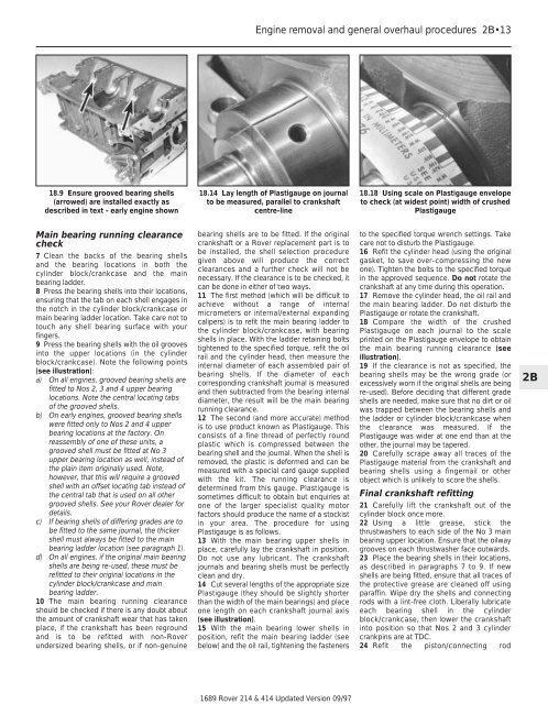
18.18 Using scale on Plastigauge envelope<br />
to check (at widest point) width of crushed<br />
Plastigauge<br />
to the specified torque wrench settings. Take<br />
care not to disturb the Plastigauge.<br />
16 Refit the cylinder head (using the original<br />
gasket, to save over-compressing the new<br />
one). Tighten the bolts to the specified torque<br />
in the approved sequence. Do not rotate the<br />
crankshaft at any time during this operation.<br />
17 Remove the cylinder head, the oil rail <strong>and</strong><br />
the main bearing ladder. Do not disturb the<br />
Plastigauge or rotate the crankshaft.<br />
18 Compare the width of the crushed<br />
Plastigauge on each journal to the scale<br />
printed on the Plastigauge envelope to obtain<br />
the main bearing running clearance (see<br />
illustration).<br />
19 If the clearance is not as specified, the<br />
bearing shells may be the wrong grade (or<br />
excessively worn if the original shells are being<br />
re-used). Before deciding that different grade<br />
shells are needed, make sure that no dirt or oil<br />
was trapped between the bearing shells <strong>and</strong><br />
the ladder or cylinder block/crankcase when<br />
the clearance was measured. If the<br />
Plastigauge was wider at one end than at the<br />
other, the journal may be tapered.<br />
20 Carefully scrape away all traces of the<br />
Plastigauge material from the crankshaft <strong>and</strong><br />
bearing shells using a fingernail or other<br />
object which is unlikely to score the shells.<br />
Final crankshaft refitting<br />
21 Carefully lift the crankshaft out of the<br />
cylinder block once more.<br />
22 Using a little grease, stick the<br />
thrustwashers to each side of the No 3 main<br />
bearing upper location. Ensure that the oilway<br />
grooves on each thrustwasher face outwards.<br />
23 Place the bearing shells in their locations,<br />
as described in paragraphs 7 to 9. If new<br />
shells are being fitted, ensure that all traces of<br />
the protective grease are cleaned off using<br />
paraffin. Wipe dry the shells <strong>and</strong> connecting<br />
rods with a lint-free cloth. Liberally lubricate<br />
each bearing shell in the cylinder<br />
block/crankcase, then lower the crankshaft<br />
into position so that Nos 2 <strong>and</strong> 3 cylinder<br />
crankpins are at TDC.<br />
24 Refit the piston/connecting rod<br />
2B