

Rover 214 & 414 Service and Repair Manual - Rover club
Rover 214 & 414 Service and Repair Manual - Rover club
Rover 214 & 414 Service and Repair Manual - Rover club

You also want an ePaper? Increase the reach of your titles
YUMPU automatically turns print PDFs into web optimized ePapers that Google loves.
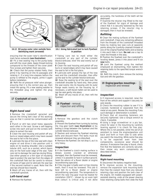
16.12 Oil pump outer rotor outside face<br />
identifying mark (arrowed)<br />
ensuring that the outer rotor’s identification<br />
mark faces outwards (see illustration).<br />
13 Fit a new sealing ring to the pump body<br />
<strong>and</strong> refit the cover plate. Apply thread-locking<br />
compound to the threads of the cover plate<br />
Torx screws <strong>and</strong> tighten them securely.<br />
14 Check that the pump rotates freely, then<br />
prime it by injecting oil into its passages <strong>and</strong><br />
rotating it. If a long time elapses before the<br />
pump is refitted to the engine, prime it again<br />
before installation.<br />
15 Refit the oil pressure relief valve plunger,<br />
ensuring that it is the correct way up, then<br />
install the spring. Fit a new sealing washer to<br />
the threaded plug <strong>and</strong> tighten the plug<br />
securely.<br />
17 Crankshaft oil seals -<br />
renewal 4<br />
Right-h<strong>and</strong> seal<br />
1 Remove the crankshaft sprocket <strong>and</strong><br />
secure the timing belt clear of the working<br />
area so that it cannot be contaminated with<br />
oil.<br />
2 Punch or drill two small holes opposite<br />
each other in the seal. Screw a self-tapping<br />
screw into each <strong>and</strong> pull on the screws with<br />
pliers to extract the seal.<br />
3 Clean the seal housing <strong>and</strong> polish off any<br />
burrs or raised edges which may have caused<br />
the seal to fail in the first place.<br />
4 Lubricate the lips of the new seal with clean<br />
engine oil <strong>and</strong> drive it into position until it<br />
seats on its locating shoulder. Use a suitable<br />
tubular drift, such as a socket, which bears<br />
only on the hard outer edge of the seal. Take<br />
care not to damage the seal lips during fitting.<br />
Use either grease or a thin layer of insulating<br />
tape to protect the seal lips from the edges of<br />
the crankshaft flats but be careful to remove<br />
all traces of tape <strong>and</strong> to lubricate the seal lips<br />
if the second method is used. Note that the<br />
seal lips should face inwards.<br />
5 Wash off any traces of oil, then refit the<br />
crankshaft sprocket.<br />
Left-h<strong>and</strong> seal<br />
6 Remove the flywheel.<br />
18.2 Using fabricated tool to lock flywheel<br />
in position<br />
7 Taking care not to mark either the<br />
crankshaft or any part of the cylinder<br />
block/crankcase, lever the seal evenly out of<br />
its housing.<br />
8 Clean the seal housing <strong>and</strong> polish off any<br />
burrs or raised edges which may have caused<br />
the seal to fail in the first place.<br />
9 Lubricate with grease the lips of the new<br />
seal <strong>and</strong> the crankshaft shoulder, then offer<br />
up the seal to the cylinder block/crankcase.<br />
10 Ease the sealing lip of the seal over the<br />
crankshaft shoulder by h<strong>and</strong> only, then press<br />
the seal evenly into its housing until its outer<br />
flange seats evenly on the housing lip. If<br />
necessary, a soft-faced mallet can be used to<br />
tap the seal gently into place.<br />
11 Wash off any traces of oil, then refit the<br />
flywheel.<br />
18 Flywheel - removal,<br />
inspection <strong>and</strong> refitting 5<br />
Removal<br />
1 Remove the gearbox <strong>and</strong> the clutch<br />
assembly.<br />
2 Prevent the flywheel from turning by locking<br />
the ring gear teeth (see illustration) or by<br />
bolting a strap between the flywheel <strong>and</strong> the<br />
cylinder block/crankcase.<br />
3 Slacken <strong>and</strong> remove the flywheel retaining<br />
bolts <strong>and</strong> discard them The bolts must be<br />
renewed whenever they are disturbed.<br />
4 Remove the flywheel. Do not drop it, as it is<br />
very heavy.<br />
Inspection<br />
5 If the flywheel’s clutch mating surface is<br />
deeply scored, cracked or otherwise<br />
damaged, then the flywheel must be renewed,<br />
unless it is possible to have it surface ground.<br />
Seek the advice of a <strong>Rover</strong> dealer or engine<br />
reconditioning specialist.<br />
6 If the ring gear is badly worn or has missing<br />
teeth, then it must be renewed. This job is<br />
best left to a <strong>Rover</strong> dealer or engine<br />
reconditioning specialist. The temperature to<br />
which the new ring gear must be heated for<br />
installation (350°C - shown by an even light<br />
blue colour) is critical <strong>and</strong>, if not done<br />
1689 <strong>Rover</strong> <strong>214</strong> & <strong>414</strong> Updated Version 09/97<br />
Engine in-car repair procedures 2A•21<br />
accurately, the hardness of the teeth will be<br />
destroyed.<br />
7 Examine the reluctor ring (fitted to the rear<br />
of the flywheel) for signs of damage <strong>and</strong><br />
check that it is securely fastened by the two<br />
retaining screws. If the reluctor ring is<br />
damaged, then it must be renewed.<br />
Refitting<br />
8 Clean the mating surfaces of the flywheel<br />
<strong>and</strong> crankshaft. Clean any remaining adhesive<br />
from the threads of the crankshaft threaded<br />
holes by making two saw cuts at opposite<br />
points along the (carefully-cleaned) threads of<br />
one of the original flywheel bolts <strong>and</strong> screwing<br />
it into each hole in turn. Do not use a tap to<br />
clean the threads in this way.<br />
9 Position the flywheel over the crankshaft’s<br />
locating dowel, press it into place <strong>and</strong> fit six<br />
new bolts.<br />
10 Lock the flywheel using the method<br />
employed on dismantling, then tighten the<br />
retaining bolts to the specified torque wrench<br />
setting.<br />
11 Refit the clutch, then remove the locking<br />
tool <strong>and</strong> refit the gearbox.<br />
19 Engine/gearbox mountings -<br />
inspection <strong>and</strong> renewal 2<br />
Inspection<br />
1 If improved access is required, raise the<br />
front of the vehicle <strong>and</strong> support it securely on<br />
axle st<strong>and</strong>s.<br />
2 Check the mounting rubber to see if it is<br />
cracked, hardened or separated from the<br />
metal at any point. Renew the mounting if any<br />
such damage or deterioration is evident.<br />
3 Check that all mounting fasteners are<br />
securely tightened. Use a torque wrench to<br />
check, if possible.<br />
4 Using a large screwdriver or a pry bar,<br />
check for wear in the mounting by carefully<br />
levering against it to check for free play.<br />
Where this is not possible, enlist the aid of an<br />
assistant to move the engine/gearbox unit<br />
back <strong>and</strong> forth or from side to side while<br />
you watch the mounting. While some free play<br />
is to be expected even from new<br />
components, excessive wear should be<br />
obvious. If excessive free play is found, check<br />
first that the fasteners are correctly secured,<br />
then renew any worn components as<br />
described below.<br />
Renewal<br />
Right-h<strong>and</strong> mounting<br />
5 Disconnect the battery negative lead.<br />
6 To improve access to the mounting,<br />
remove the expansion tank mounting bolts<br />
then free the coolant hose from any relevant<br />
retaining clips <strong>and</strong> position the tank clear of<br />
the engine. On models equipped with powerassisted<br />
steering, undo all the power steering<br />
hose retaining clamp bolts then slide the fluid<br />
2A