- Page 1 and 2:
Facoltà di Ingegneria Dipartimento
- Page 3 and 4:
CAPITOLO 2 2. La concentrazione del
- Page 5 and 6:
6. Il simulatore solare…………
- Page 7 and 8:
di processi per la produzione dell
- Page 9 and 10:
L’affermazione del supporto idrog
- Page 11 and 12:
4. Combinazione del reforming con v
- Page 13 and 14:
Altra strada praticata è quella ch
- Page 15 and 16:
Per quanto riguarda la produzione d
- Page 17 and 18:
dell’acqua avviene grazie alla pr
- Page 19 and 20:
fisso, il flusso gassoso attraverso
- Page 21 and 22:
Un impianto UT-3 è stato realizzat
- Page 23 and 24:
Nella seconda reazione sopra riport
- Page 25 and 26:
Figura1.5 Rappresentazione schemati
- Page 27 and 28:
eazioni globali, il coinvolgimento
- Page 29 and 30:
Se comparato con il ciclo WH, tale
- Page 31 and 32:
3 FeCl2(s) + 4 H2O(g) → Fe3O4(s)
- Page 33 and 34:
Sezione 2 (H 2SO 4+4H 2O)⇒ (H 2SO
- Page 35 and 36:
• Decomposizione di SO3 secondo l
- Page 37 and 38:
In particolare Fedders et al. hanno
- Page 39 and 40:
una miscela acqua-acido solforico c
- Page 41 and 42:
T1: Torre di separazione di SO3; HX
- Page 43 and 44:
quanto descritto in precedenza, nel
- Page 45 and 46:
Tale arrangiamento risulta essere u
- Page 47 and 48:
La pressione viene incrementata (po
- Page 49 and 50:
Figura 1.13. Flowsheet per la sezio
- Page 51 and 52:
punto da GA, pur essendo il più di
- Page 53 and 54:
Figura 1.14: Schema di processo ENE
- Page 55 and 56:
In figura 1.15 è riportato in dett
- Page 57 and 58:
Nel totale il calore richiesto per
- Page 59 and 60:
sistema di captazione e concentrazi
- Page 61 and 62:
L’energia raggiante che viene tra
- Page 63 and 64:
La radiazione elettromagnetica prov
- Page 65 and 66:
ore centrali della giornata avrà u
- Page 67 and 68:
La radiazione diffusa appare unifor
- Page 69 and 70:
a) b) c) d) Figura 4.5. Esempi di a
- Page 71 and 72:
Figura 2.6. Angolo azimutale L’or
- Page 73 and 74:
Tutti questi aspetti di carattere g
- Page 75 and 76:
Figura 2.8. Schema concentratore pa
- Page 77 and 78:
Figura 2.11. Esempio di concentrato
- Page 79 and 80:
Figura 2.13. Impianto a torre solar
- Page 81 and 82:
Tale legge, per il caso presentato
- Page 83 and 84:
Le perdite imputabili a questi ulti
- Page 85 and 86:
Il rendimento di spillamento ( η s
- Page 87 and 88:
Percentage Loss Design Point, Annua
- Page 89 and 90:
Con il presente lavoro si è cercat
- Page 91 and 92:
forze centrifughe generate dalla ro
- Page 93 and 94:
Figura 3.2. Schema del “two cavit
- Page 95 and 96:
l’utilizzo di un gas ausiliario c
- Page 97 and 98:
5) “Volumetric reactor”: Figura
- Page 99 and 100:
Treactor, Qsolar è il valore della
- Page 101 and 102:
Dagli esperimenti non emergono segn
- Page 103 and 104:
l’accumulo termico. Ciascuna fasc
- Page 105 and 106:
Figura 3.8. Rappresentazione 3D del
- Page 107 and 108:
igenerazione. Con tali metodi è st
- Page 109 and 110:
termici sulle pareti dei tubi di ol
- Page 111 and 112:
dei tubi rivolti verso l’asse del
- Page 113 and 114:
• Buona resistenza meccanica in m
- Page 115 and 116:
Figura 3.14: Geometria della finest
- Page 117 and 118:
Kribus A., Doron P., Rubin R., Karn
- Page 119 and 120:
Ries H., Kribus A., Karni J., Non-i
- Page 121 and 122:
C. A. LaJeunesse et al., “Thermal
- Page 123 and 124:
Dall’analisi si evince che sia la
- Page 125 and 126:
Nel grafico 3.23 si nota come l’
- Page 127 and 128:
UNLV Research Foundation, High temp
- Page 129 and 130:
De Bernardez E.R., Claria M.A., Cas
- Page 131 and 132:
3.3 Considerazioni sullo stato dell
- Page 133 and 134:
l’assenza della finestra traspare
- Page 135 and 136:
una superficie ideale nera posta su
- Page 137 and 138:
mantenere pulita la finestra a caus
- Page 139 and 140:
solare concentrata impingente sulla
- Page 141 and 142:
Sarà, quindi, necessario esplorare
- Page 143 and 144:
3.1 Bibliografia PSI (Paul Scherrer
- Page 145 and 146:
[15] Guesdon C., Development of a m
- Page 147 and 148:
[30] Adinberg R., Epstein M., Exper
- Page 149 and 150:
[47] Kläup S., Steinfeld A., Exper
- Page 151 and 152:
MIR Space Station, 30 th Intersocie
- Page 153 and 154:
[80] Miron G., Assis E., Erez A., T
- Page 155 and 156:
[96] Alexander D., 2kWe Solar Dynam
- Page 157 and 158:
destination of thermophysical and h
- Page 159 and 160:
[124] Roeb M., Sattler C., Klüser
- Page 161 and 162:
membranes for a solar thermal water
- Page 163 and 164:
[153] Kribus A., Timinger A., Optic
- Page 165 and 166:
[167] Kodama T., Kondoh Y., Tamagaw
- Page 167 and 168:
[182]Romero M., Buck R., Pacheco J.
- Page 169 and 170:
[198] Bing Du, Liang-Shih Fan, Fei
- Page 171 and 172:
condizioni di esercizio come, ad es
- Page 173 and 174:
4.2 Modellizzazione di reattori a c
- Page 175 and 176:
4.2.1 Metodi di risoluzione ai volu
- Page 177 and 178:
Posizione della componente u della
- Page 179 and 180:
dove φ rappresenta la grandezza sc
- Page 181 and 182:
Per calcolare i termini convettivi
- Page 183 and 184:
semplificato nel quale le gocce di
- Page 185 and 186:
Entrambi gli aspetti sono piuttosto
- Page 187 and 188:
Figura 4.10: Distribuzione della fr
- Page 189 and 190:
iesce a vaporizzare completamente p
- Page 191 and 192:
4.2.3 Modellizzazione e simulazioni
- Page 193 and 194:
foam honeycomb structure Figura 4.1
- Page 195 and 196:
• Radiazione concentrata a raggi
- Page 197 and 198:
4.18) conforme alla geometria del p
- Page 199 and 200:
Come è possibile notare in fig. 4.
- Page 201 and 202:
Vapour sources Vaporizer Figura 4.2
- Page 203 and 204:
considerazioni in seguito sono stat
- Page 205 and 206:
Anche le ipotesi assunte sugli scam
- Page 207 and 208:
Fig. 4.29: Distribuzione della fraz
- Page 209 and 210:
4.3 Reattore solare scala laborator
- Page 211 and 212:
isolante; (3) Finestra ottica; (4)
- Page 213 and 214:
Il reattore è costituito da un cil
- Page 215 and 216:
temperature misurate da una termoco
- Page 217 and 218:
Con questo montaggio sperimentale
- Page 219 and 220:
di ciascun profilo) e le zone fredd
- Page 221 and 222:
Figura 4.38: Profilo termico della
- Page 223 and 224: processo può essere scisso in 3 re
- Page 225 and 226: Figura 4.39. Andamento del fattore
- Page 227 and 228: 5.1 Introduzione CAPITOLO 5 Ricevit
- Page 229 and 230: stato individuato quale mezzo poten
- Page 231 and 232: Figura 5.1: Schema esemplificativa
- Page 233 and 234: In tali condizioni l’energia sola
- Page 235 and 236: L’efficienza di captazione misura
- Page 237 and 238: eirraggiamento quelle dovute a tale
- Page 239 and 240: Con δkj è delta di Kronecker. N 4
- Page 241 and 242: 5.3.1 Primo prototipo Per poter ver
- Page 243 and 244: Figura 5.16: Esploso del mantello e
- Page 245 and 246: Figura 5.18: Disegno esecutivo dell
- Page 247 and 248: Si prevede di alloggiare tale strut
- Page 249 and 250: Figura 5.21: Sezione del captatore
- Page 251 and 252: • Qirr,m,p = θm σ0 Tm 4 Fm-f (
- Page 253 and 254: (10) Nu = (α dp) / λf (11) Qu = Q
- Page 255 and 256: Pagina - 255 - di 305
- Page 257 and 258: Pagina - 257 - di 305
- Page 259 and 260: Tfin Pagina - 259 - di 305
- Page 261 and 262: Tfin Pagina - 261 - di 305
- Page 263 and 264: ANALISI DEI DATI PER L’AZOTO (N2)
- Page 265 and 266: Pagina - 265 - di 305
- Page 267 and 268: Graf. 4.21 Pagina - 267 - di 305
- Page 269 and 270: Graf. 4.24 Tfin Pagina - 269 - di 3
- Page 271 and 272: Tfin Pagina - 271 - di 305
- Page 273: Tfin Pagina - 273 - di 305
- Page 277 and 278: Confrontandola con la tensione mass
- Page 279 and 280: Confronto tubi lisci - tubi corruga
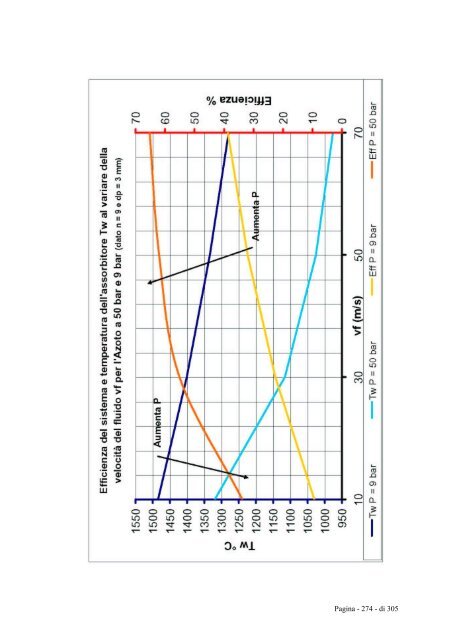
- Page 281 and 282: Andamento dell'efficienza del siste
- Page 283 and 284: 6.1 Introduzione CAPITOLO 6 Il simu
- Page 285 and 286: La zona dove sono sistemate le lamp
- Page 287 and 288: • allo xenon; • ad alogenuri me
- Page 289 and 290: Il raddrizzatore è un apparecchio
- Page 291 and 292: Per ovviare a tale problema si è p
- Page 293 and 294: inclinazione α variabile tra 0 e 9
- Page 295 and 296: Tramite un programma di ottimizzazi
- Page 297 and 298: Pagina - 297 - di 305
- Page 299 and 300: Conclusioni Nel presente lavoro è
- Page 301 and 302: Non potendo essere effettuata una s
- Page 303 and 304: A seguito di tali risultati prelimi
- Page 305: Sakurai M., Nakajiama H., Amir R.,