
Sie wollen auch ein ePaper? Erhöhen Sie die Reichweite Ihrer Titel.
YUMPU macht aus Druck-PDFs automatisch weboptimierte ePaper, die Google liebt.
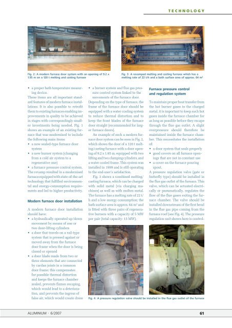
Fig. 2: A mo<strong>de</strong>rn furnace door system with an opening of 9.2 x<br />
1.95 m on a 120 t melting and casting furnace<br />
• a proper bath temperature measuring<br />
<strong>de</strong>vice.<br />
These items are all important standard<br />
features of mo<strong>de</strong>rn furnace installations.<br />
It is also possible to retrofit<br />
them to existing furnaces enabling improvements<br />
in quality to be achieved<br />
in stages with correspondingly smaller<br />
investments being nee<strong>de</strong>d. Fig. 1<br />
shows an example of an existing furnace<br />
that was mo<strong>de</strong>rnised to inclu<strong>de</strong><br />
the following main items:<br />
• a new sealed-type furnace door<br />
system<br />
• a new burner system (changing<br />
from a cold air system to a<br />
regenerative one)<br />
• a furnace pressure control system.<br />
The revamp resulted in a mo<strong>de</strong>rnised<br />
furnace equipped with state-of-the-art<br />
technology that fulfilled environmental<br />
and energy-consumption requirements<br />
and led to higher productivity.<br />
Mo<strong>de</strong>rn furnace door installation<br />
A mo<strong>de</strong>rn furnace door installation<br />
should have:<br />
• a hydraulically operated up/down<br />
movement by means of one or<br />
two door-lifting cylin<strong>de</strong>rs<br />
• a door that travels on a rail-type<br />
system that is pressed against or<br />
moved away from the furnace<br />
door frame when the door is being<br />
closed or opened<br />
• a door bla<strong>de</strong> ma<strong>de</strong> from two or<br />
three elements that are connected<br />
by cardan joints in a common<br />
door frame; this compensates<br />
for possible thermal distortion<br />
and keeps the furnace chamber<br />
sealed, prevents flames escaping,<br />
which would lead to a <strong>de</strong>teriora-<br />
tion, and prevents the ingress of<br />
false air, which would create dross<br />
ALUMINIUM · 6/2007<br />
• a burner system and flue gas pres-<br />
sure control system linked to the<br />
movements of the furnace door.<br />
Depending on the type of furnace, the<br />
frame of the furnace door should be<br />
equipped with a water cooling system<br />
to reduce thermal distortion and to<br />
keep the front bla<strong>de</strong>s of the furnace<br />
door straight (recommen<strong>de</strong>d for larger<br />
furnace doors).<br />
An example of such a mo<strong>de</strong>rn furnace<br />
door system can be seen in Fig. 2,<br />
which shows the door of a 120 t melting/casting<br />
furnace with a door opening<br />
of 9.2 x 1.95 m, equipped with two<br />
lifting and two clamping cylin<strong>de</strong>rs, and<br />
a water cooled frame. This system was<br />
installed in 1999 and is still operating<br />
to the end-user’s satisfaction.<br />
Fig. 3 shows a combined melting/<br />
casting furnace, which can be charged<br />
with solid metal (via charging machines)<br />
as well as with molten metal.<br />
The furnace has a melting rate of 22 t/<br />
h and a low energy consumption; the<br />
bath surface area is approx. 64 m 2 and<br />
is fitted with three pairs of regenerative<br />
burners with a capacity of 5 MW<br />
per pair (total capacity: 15 MW).<br />
TECHNOLOGY<br />
Fig. 3: A revamped melting and casting furnace which has a<br />
melting rate of 22 t/h and a bath surface area of approx. 64 m 2<br />
Furnace pressure control<br />
and regulation system<br />
To maintain proper heat transfer from<br />
the hot burner gases to the charged<br />
metal, it is important to keep such hot<br />
gases insi<strong>de</strong> the furnace chamber for<br />
as long as possible before they escape<br />
through the flue gas outlet. A slight<br />
overpressure should therefore be<br />
maintained insi<strong>de</strong> the furnace chamber.<br />
This necessitates the installation<br />
of:<br />
• a door system that seals properly<br />
• good covers on all furnace open-<br />
ings that are not in constant use<br />
• a cover on the furnace pouring<br />
spout.<br />
A pressure regulation valve (gate or<br />
butterfly type) should be installed in<br />
the flue gas outlet of the furnace. This<br />
valve, which can be actuated electrically<br />
or pneumatically, regulates the<br />
flow of the flue gases exiting the furnace<br />
chamber. The valve should be<br />
installed downstream of the first bend<br />
in the flue gas pipe coming from the<br />
furnace roof (see Fig. 4). The pressure<br />
regulation unit shown here is control-<br />
Fig. 4: A pressure regulation valve should be installed in the flue gas outlet of the furnace<br />
61