
Erfolgreiche ePaper selbst erstellen
Machen Sie aus Ihren PDF Publikationen ein blätterbares Flipbook mit unserer einzigartigen Google optimierten e-Paper Software.
TECHNOLOGY<br />
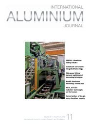
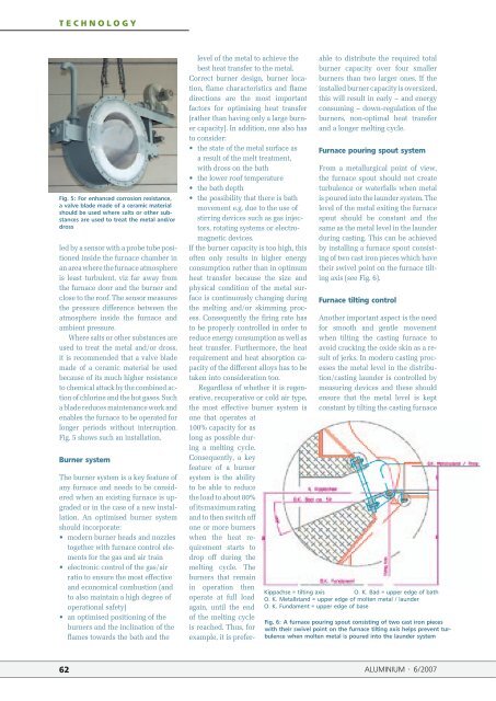
Fig. 5: For enhanced corrosion resistance,<br />
a valve bla<strong>de</strong> ma<strong>de</strong> of a ceramic material<br />
should be used where salts or other substances<br />
are used to treat the metal and/or<br />
dross<br />
led by a sensor with a probe tube positioned<br />
insi<strong>de</strong> the furnace chamber in<br />
an area where the furnace atmosphere<br />
is least turbulent, viz far away from<br />
the furnace door and the burner and<br />
close to the roof. The sensor measures<br />
the pressure difference between the<br />
atmosphere insi<strong>de</strong> the furnace and<br />
ambient pressure.<br />
Where salts or other substances are<br />
used to treat the metal and/or dross,<br />
it is recommen<strong>de</strong>d that a valve bla<strong>de</strong><br />
ma<strong>de</strong> of a ceramic material be used<br />
because of its much higher resistance<br />
to chemical attack by the combined action<br />
of chlorine and the hot gases. Such<br />
a bla<strong>de</strong> reduces maintenance work and<br />
enables the furnace to be operated for<br />
longer periods without interruption.<br />
Fig. 5 shows such an installation.<br />
Burner system<br />
The burner system is a key feature of<br />
any furnace and needs to be consi<strong>de</strong>red<br />
when an existing furnace is upgra<strong>de</strong>d<br />
or in the case of a new installation.<br />
An optimised burner system<br />
should incorporate:<br />
• mo<strong>de</strong>rn burner heads and nozzles<br />
together with furnace control elements<br />
for the gas and air train<br />
• electronic control of the gas/air<br />
ratio to ensure the most effective<br />
and economical combustion (and<br />
to also maintain a high <strong>de</strong>gree of<br />
operational safety)<br />
• an optimised positioning of the<br />
burners and the inclination of the<br />
flames towards the bath and the<br />
level of the metal to achieve the<br />
best heat transfer to the metal.<br />
Correct burner <strong>de</strong>sign, burner location,<br />
flame characteristics and flame<br />
directions are the most important<br />
factors for optimising heat transfer<br />
(rather than having only a large burner<br />
capacity). In addition, one also has<br />
to consi<strong>de</strong>r:<br />
• the state of the metal surface as<br />
a result of the melt treatment,<br />
with dross on the bath<br />
• the lower roof temperature<br />
• the bath <strong>de</strong>pth<br />
• the possibility that there is bath<br />
movement e.g. due to the use of<br />
stirring <strong>de</strong>vices such as gas injec-<br />
tors, rotating systems or electro-<br />
magnetic <strong>de</strong>vices.<br />
If the burner capacity is too high, this<br />
often only results in higher energy<br />
consumption rather than in optimum<br />
heat transfer because the size and<br />
physical condition of the metal surface<br />
is continuously changing during<br />
the melting and/or skimming process.<br />
Consequently the firing rate has<br />
to be properly controlled in or<strong>de</strong>r to<br />
reduce energy consumption as well as<br />
heat transfer. Furthermore, the heat<br />
requirement and heat absorption capacity<br />
of the different alloys has to be<br />
taken into consi<strong>de</strong>ration too.<br />
Regardless of whether it is regenerative,<br />
recuperative or cold air type,<br />
the most effective burner system is<br />
one that operates at<br />
100% capacity for as<br />
long as possible during<br />
a melting cycle.<br />
Consequently, a key<br />
feature of a burner<br />
system is the ability<br />
to be able to reduce<br />
the load to about 80%<br />
of its maximum rating<br />
and to then switch off<br />
one or more burners<br />
when the heat requirement<br />
starts to<br />
drop off during the<br />
melting cycle. The<br />
burners that remain<br />
in operation then<br />
operate at full load<br />
again, until the end<br />
of the melting cycle<br />
is reached. Thus, for<br />
example, it is prefer-<br />
able to distribute the required total<br />
burner capacity over four smaller<br />
burners than two larger ones. If the<br />
installed burner capacity is oversized,<br />
this will result in early – and energy<br />
consuming – down-regulation of the<br />
burners, non-optimal heat transfer<br />
and a longer melting cycle.<br />
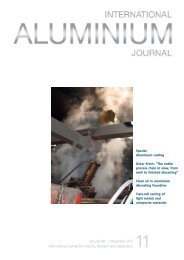
Furnace pouring spout system<br />
From a metallurgical point of view,<br />
the furnace spout should not create<br />
turbulence or waterfalls when metal<br />
is poured into the laun<strong>de</strong>r system. The<br />
level of the metal exiting the furnace<br />
spout should be constant and the<br />
same as the metal level in the laun<strong>de</strong>r<br />
during casting. This can be achieved<br />
by installing a furnace spout consisting<br />
of two cast iron pieces which have<br />
their swivel point on the furnace tilting<br />
axis (see Fig. 6).<br />
Furnace tilting control<br />
Another important aspect is the need<br />
for smooth and gentle movement<br />
when tilting the casting furnace to<br />
avoid cracking the oxi<strong>de</strong> skin as a result<br />
of jerks. In mo<strong>de</strong>rn casting processes<br />
the metal level in the distribution/casting<br />
laun<strong>de</strong>r is controlled by<br />
measuring <strong>de</strong>vices and these should<br />
ensure that the metal level is kept<br />
constant by tilting the casting furnace<br />
Kippachse = tilting axis O. K. Bad = upper edge of bath<br />
O. K. Metallstand = upper edge of molten metal / laun<strong>de</strong>r<br />
O. K. Fundament = upper edge of base<br />
Fig. 6: A furnace pouring spout consisting of two cast iron pieces<br />
with their swivel point on the furnace tilting axis helps prevent turbulence<br />
when molten metal is poured into the laun<strong>de</strong>r system<br />
62 ALUMINIUM · 6/2007