WSCAD 5.2 - FTP Directory Listing
WSCAD 5.2 - FTP Directory Listing
WSCAD 5.2 - FTP Directory Listing

You also want an ePaper? Increase the reach of your titles
YUMPU automatically turns print PDFs into web optimized ePapers that Google loves.
Hint<br />
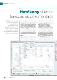
Design capture<br />
Obviously we would not need an Input and an Output module for our small<br />
example. This serves only to demonstrate the functions of the PLC<br />
manager.<br />
You may have realized that there is no cross-reference at this time. However, as we<br />
have not yet loaded the PLC main module, cross-referencing is not yet possible.<br />
Now we have to load two digital outputs for the control of the valves -Q1 and –Q2.<br />
Place them but at this time with a double click with the left mouse button.<br />
This allows you to skip the database selection dialog (which is not needed here) and<br />
to make the channel allocation directly. (If you do accidentally activate the<br />
database, simply exit it and this will take you to the assignment menu). Assign the<br />
outputs for –Q1 or –Q2 to the digital output 'Digital Output SM 322-1BH00<br />
16x24V DC' (Function text: '!Table control'). Enter the PLC text for both valves<br />
-Q1 and -Q2 as: 'Table up' and 'Table down’.<br />
Tip<br />
A double click when loading the PLC main module takes you directly to the<br />
assignment of this symbol to a PLC module the PLC manager is already<br />
controlling. The rule is: every selection in the database menu creates a new<br />
PLC module in the 'PLC selection', so whenever you double click or quit out<br />
of the database selection window, the assignment menu will always<br />
appear. You can still delete any symbol with the 'Delete' command.<br />
The database dialog is not necessary because we have already set the parameters<br />
by inserting the individual PLC connection. Now you only need to assign the symbol<br />
to a PLC module controlled by the 'PLC selection'. Main modules which have not<br />
yet been assigned are marked with a '*'. These are 'virtual' PLC modules.<br />
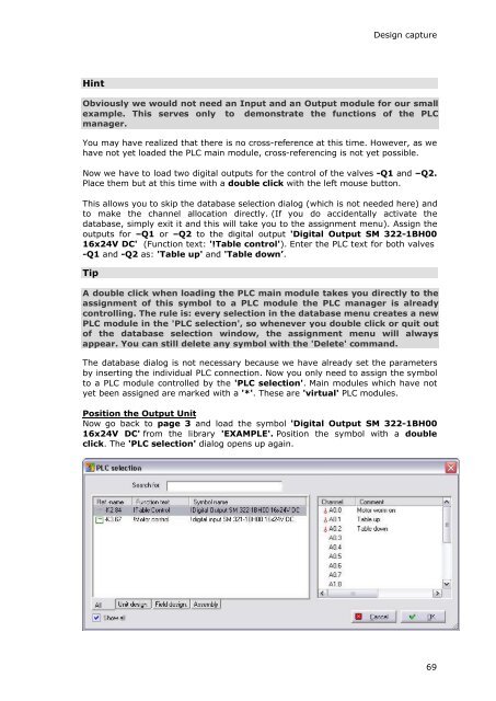
Position the Output Unit<br />
Now go back to page 3 and load the symbol 'Digital Output SM 322-1BH00<br />
16x24V DC' from the library 'EXAMPLE'. Position the symbol with a double<br />
click. The 'PLC selection' dialog opens up again.<br />
69