- Page 1 and 2:
Operation and Service Guide HP 8648
- Page 3 and 4:
Certification Warranty Hewlett-Pack
- Page 5 and 6:
Instrument Support Center Hewlett-P
- Page 7 and 8:
General Safety Considerations Warni
- Page 9 and 10:
Contents 1. Operation Quick Overvie
- Page 11 and 12:
Message During Servicing . . . . .
- Page 13 and 14:
POWer Subsystem . . . . . . . . . .
- Page 15 and 16:
AM Modulator . . . . . . . . . . .
- Page 17 and 18:
Figures 2-l. HP 8648 Status Registe
- Page 19 and 20:
7-68. Using the Open Dialog Box to
- Page 21 and 22:
8-29. AM Accuracy Performance Test
- Page 23 and 24:
Operation “Operation” contains
- Page 25 and 26:
The following table describes the p
- Page 27 and 28:
7. Modulation Source Press CMOD ON/
- Page 29 and 30:
Operation Examples This section pro
- Page 31 and 32:
Turn on the RF Output 3. Press C-1
- Page 33 and 34:
Using the Increment 3. Enter a freq
- Page 35 and 36:
Saving Instrument In this ten step
- Page 37 and 38:
egseq9.dw la-l 0 Operation Examples
- Page 39 and 40:
I Deleting a Register In this examp
- Page 41 and 42:
Renumbering the In this example, yo
- Page 43 and 44:
Inserting a Register in In this exa
- Page 45 and 46:
Offsetting the RF Output from a Ref
- Page 47 and 48:
la-20 Operation Examples 6. Change
- Page 49 and 50:
la-22 Operation Examples Adjusting
- Page 51 and 52:
Setting the Modulated 2. Press the
- Page 53 and 54:
Setting Up Pager The following step
- Page 55 and 56:
Selecting the Data 3. Set DATA RATE
- Page 57 and 58:
Selecting the Pager Capcode (Addres
- Page 59 and 60:
Selecting the Roaming 11. Set ROAMI
- Page 61 and 62:
Frequency/Amplitude Frequency and A
- Page 63 and 64:
Function Function hmckeys.drw 1. FR
- Page 65 and 66:
Function Setting Up the Pager Encod
- Page 67 and 68:
Function Setting the Format The for
- Page 69 and 70:
Function lb-10 Operation Reference
- Page 71 and 72:
Function lb-12 Operation Reference
- Page 73 and 74:
Function lb-14 Operation Reference
- Page 75 and 76:
Function lb-16 Operation Reference
- Page 77 and 78:
Function I- / I I / 1’gMRl 0 non
- Page 79 and 80:
Function lb-20 Operation Reference
- Page 81 and 82:
Function 1 b-22 Operation Reference
- Page 83 and 84:
Function 1 b-24 Operation Reference
- Page 85 and 86:
Function 1 b-26 Operation Reference
- Page 87 and 88:
Function 1 b-28 Operation Reference
- Page 89 and 90:
Function lb-30 Operation Reference
- Page 91 and 92:
Function mmiii\ FREQUENCY 1 b-32 Op
- Page 93 and 94:
Function PN15 Setting the Data Rate
- Page 95 and 96:
Pulse Modulation Pulse Modulation N
- Page 97 and 98:
Increment Set Increment Set 1 b-38
- Page 99 and 100:
1 b-40 Operation Reference 2. Backs
- Page 101 and 102:
Instrument Preset lb-42 Operation R
- Page 103 and 104:
Instrument Preset 1 b-44 Operation
- Page 105 and 106:
Memory Memory The memory keys allow
- Page 107 and 108:
Memory 3. Register Recall The recal
- Page 109 and 110:
Modulation Source Modulation Source
- Page 111 and 112:
Modulation Source Note 5. EXT AC EX
- Page 113 and 114:
RF output RF Output 1. RF ON/OFF Pr
- Page 115 and 116:
Rear Panel Operation Rear Panel 1.
- Page 117 and 118:
Remote Interface Remote Interface (
- Page 119 and 120:
Memory Interface Memory Interface (
- Page 121 and 122:
Operation Messages Front Panel Oper
- Page 123 and 124:
011 017 Amplitude exceeds ATTN HOLD
- Page 125 and 126:
HP-IB - Command Errors -101 -102 -1
- Page 127 and 128:
HP-IB Execution Errors HP-IB Device
- Page 129 and 130:
HP-IB Programming Background This s
- Page 131 and 132:
Programming Examples Examples are p
- Page 133 and 134:
Programming Pager 188 I~IJTF’IJT
- Page 135 and 136:
Command Statement Description Query
- Page 137 and 138:
%ble 2-1. Programming Command State
- Page 139 and 140:
‘Ihble 2-1. Programming Command S
- Page 141 and 142:
Ftwer6e Pwmr UnspecMed Amplkde Ext.
- Page 143 and 144:
Example: Generate a Service Request
- Page 145 and 146:
Unspecified Power This instrument p
- Page 147 and 148:
Line 50 Clears all status registers
- Page 149 and 150:
ABORt Subsystem ABORt (Option 1EP O
- Page 151 and 152:
Note FM Subsystem To set or change
- Page 153 and 154:
PAGing Subsystem [SOURceI (Option 1
- Page 155 and 156:
The contents of data to be filled i
- Page 157 and 158:
Note The data to be sent by the :DE
- Page 159 and 160:
[SOURce] : PAGing C : FORMatI :{FLE
- Page 161 and 162: [SOURceI : PAGing C : FORMat] :
- Page 163 and 164: [SOURceI :PAGing [:FORMat] :(FLEXIF
- Page 165 and 166: PM Subsystem [SOURceI :PM [:DEViati
- Page 167 and 168: STATUS Subsystem STATUS :QUEStionab
- Page 169 and 170: Changing Parameters While Encoding
- Page 171 and 172: HP-IB Capabilities The instrument i
- Page 173 and 174: HP 8656157 Compatible Language The
- Page 175 and 176: 9-0~till Code* RC RL RP RO Rl R2 R3
- Page 177 and 178: Installation Unpacking Your 1. Unpa
- Page 179 and 180: Replacing the Fuse If a fuse failur
- Page 181 and 182: Turning On the Signal Generator Con
- Page 183 and 184: Specifications Options This chapter
- Page 185 and 186: output 10 MHZ, typically > 0.5 Vm l
- Page 187 and 188: Nonharmonics (2 5 kHz offset, < + 4
- Page 189 and 190: Resolution < 2001 MHz 2 2001 MHz De
- Page 191 and 192: Environmental Operating temperature
- Page 193 and 194: output Front Panel BNC Nominally 1
- Page 195 and 196: Regulatory Information IS0 9002 Com
- Page 197 and 198: Service Ship]ping Your This chapter
- Page 199 and 200: Instrument rrequency Counter +equen
- Page 201 and 202: Post-Repair ‘able 5-2. Adjustment
- Page 203 and 204: ‘Ihble 5-3. Adjustments and Perfo
- Page 205 and 206: Theory of Operation Introduction Us
- Page 207 and 208: Overview The HP 8648A/B/C/D signal
- Page 209 and 210: A2 Power Supply The power supply is
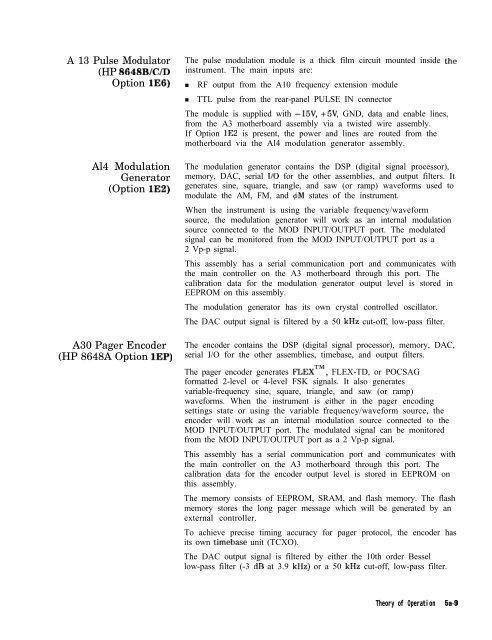
- Page 211: A6 Output (HP 8648A) The output ass
- Page 215 and 216: Troubleshooting Checklist 0 Li Ll D
- Page 217 and 218: Modulation Test Points and Power Su
- Page 220: jA30 PAGER ENCODER (OPT 1EP) ! ,~,
- Page 224 and 225: 502 Service Error Messages 506 Desc
- Page 226 and 227: 5c-4 Service Error Messages 512 Des
- Page 228 and 229: 5c-6 Service Error Messages 604 Des
- Page 230 and 231: 5c-8 Service Error Messages 618 Des
- Page 232 and 233: Replaceable Parts Introduction Asse
- Page 234 and 235: Al AlAl AlA AlA AlA AlJl AlMPl 41MP
- Page 236 and 237: w14 WI5 W16 w17 Wl8 Item able 6-1.
- Page 238 and 239: I ,I/.” All MI-LO LIP12 I MP25 Fi
- Page 240 and 241: A10 All Al2 Al3 Al4 Bl Fl MPl MP2 M
- Page 242 and 243: Adjustments This chapter documents
- Page 244 and 245: 2 Crimp , Connector ( 6 ) &Pin Conn
- Page 246 and 247: Internal Reference Oscillator Adjus
- Page 248 and 249: Pager Encoder Timebase Frequency Ad
- Page 250 and 251: AM Level and Distortion HP 86488 On
- Page 252 and 253: AM Level HP 8648B/C/D Only Descript
- Page 254 and 255: Detector Offset HP 8648A Only Descr
- Page 256 and 257: AM Level: FE HP 8648B/C/D Only (Not
- Page 258 and 259: Predistortion and Detector Offset H
- Page 260 and 261: Output Level: Frequency Extension C
- Page 262 and 263:
A3 Motherboard Figure 7-21. Locatio
- Page 264 and 265:
Motherboard Audio Path All HP 8648A
- Page 266 and 267:
DCFM All HP 8648A/B/C/D Description
- Page 268 and 269:
HF Power Level Accuracy All HP 8648
- Page 270 and 271:
1 \ # I J @g@ ggjJ;o P~EEB~B~QH 6dB
- Page 272 and 273:
LF Power Level Accuracy All HP 8648
- Page 274 and 275:
FSK Deviation Option 1EP Only FSK D
- Page 276 and 277:
Service Support Software The Servic
- Page 278 and 279:
4. Continue with the setup by selec
- Page 280 and 281:
Note 8. Continue with the setup by
- Page 282 and 283:
emember, you must restart MS Window
- Page 284 and 285:
2. Once the User Information dialog
- Page 286 and 287:
d. Select the Add button to add the
- Page 288 and 289:
Running the Tests and Adjustments ,
- Page 290 and 291:
Printing the Test and Adjustment Re
- Page 292 and 293:
. In the Password field (item 2), t
- Page 294 and 295:
in measurements using the power sen
- Page 296 and 297:
Editing Test Equipment Editing of t
- Page 298 and 299:
j&tapsckt... Test Equipment... Prin
- Page 300 and 301:
Removing Device Drivers Removal of
- Page 302 and 303:
Figure 7-63. Adding a Test Driver U
- Page 304 and 305:
Adding Datapacks The addition of da
- Page 306 and 307:
Removing Datapacks Removal of datap
- Page 308 and 309:
HP-IB Address In the HP8648 Motherb
- Page 310 and 311:
FhRud hth Ih* PDllam 0°C 1 you ham
- Page 312 and 313:
Caution “lea tdaMtion , RoEoed -
- Page 314 and 315:
Performance lksts Calibration Cycle
- Page 316 and 317:
HP 438 Power Meter Instrumentation
- Page 318 and 319:
Performance Tkst Descriptions The p
- Page 320 and 321:
Connect the Test Equipment Note Con
- Page 322 and 323:
HP 8648B/C/D Option lE2 Only Connec
- Page 324 and 325:
‘l&t Record HP 8648BKYD Only Conn
- Page 326 and 327:
AM Accuracy Performance Tkst (Optio
- Page 328 and 329:
Phase Modulation Distortion Perform
- Page 330 and 331:
Residual FM Performance Test Connec
- Page 332 and 333:
Harmonics Performance Tkst Connect
- Page 334 and 335:
DC FM Frequency Error Performance T
- Page 336 and 337:
Configure the HP 8648 1. Turn the R
- Page 338 and 339:
‘I&ble 8-1. High Power Level Accu
- Page 340 and 341:
Pulse Modulation Rise Time Performa
- Page 342 and 343:
Pager Encoder Timebase Accuracy Per
- Page 344 and 345:
Note FSK Deviation Accuracy Perform
- Page 346 and 347:
Symbol 0 0 0=0-Q Marker Desired Dev
- Page 348 and 349:
Internal Timebase: Aging Rate Perfo
- Page 350 and 351:
Measure the Phase Change Time Note
- Page 352 and 353:
Power Level Accuracy Performance Te
- Page 354 and 355:
HP 8648A ‘l&t Record ‘lhble 8-3
- Page 356 and 357:
‘able 8-5. FM Accuracy Performanc
- Page 358 and 359:
‘Ihble 8-7. FM Distortion Perform
- Page 360 and 361:
Amplitude (am) -6 HP 8648A Test Rec
- Page 362 and 363:
EIP 8648A Test Record Table 8-9. AM
- Page 364 and 365:
RF Frequency HP 8648A (MW 10 100 24
- Page 366 and 367:
Amplitude WW 4 -6 ‘able 8-14. Spu
- Page 368 and 369:
HP 8648A Test Record Note If the au
- Page 370 and 371:
EIP 8648A Test Record ‘able 8-16.
- Page 372 and 373:
Frequency NW 999.9 HP 8648A Test Re
- Page 374 and 375:
HP 8648B ‘I&t Record ‘able 8-20
- Page 376 and 377:
RF Frequency HP 8648B WW 1500 1500
- Page 378 and 379:
HP 8648B Test Record ‘Ihble 8-26.
- Page 380 and 381:
HP 8648B Test Record ‘I’kble 8-
- Page 382 and 383:
BP 8648B Test Record ‘Ihble 8-29.
- Page 384 and 385:
IIP 8648B Test Record ‘Ihble 8-31
- Page 386 and 387:
‘Ihble 8-35. Spurious Performance
- Page 388 and 389:
EIP 8648B Test Record Note If the a
- Page 390 and 391:
Frequency WW 400 HP 8648B Test Reco
- Page 392 and 393:
HP 8648B Test Record ‘able 8-37.
- Page 394 and 395:
HP 8648B Test Record If the automat
- Page 396 and 397:
HP 8648B Test Record ‘Ihble S-43.
- Page 398 and 399:
HP 8648C Test Record I%ble 8-46. HP
- Page 400 and 401:
HP 8648C Test Record 8-88 Performan
- Page 402 and 403:
FIP 8648C Test Record E-90 Performa
- Page 404 and 405:
HP 8648C Test Record 8-92 Performan
- Page 406 and 407:
HP 8648C Test Record 8-94 Performan
- Page 408 and 409:
HP 8648C Test Record 6-96 Performan
- Page 410 and 411:
HP 8648C Test Record 8-98 Performan
- Page 412 and 413:
HP 8648C Test Record 8-l 00 Perform
- Page 414 and 415:
HP 8648C Test Record E-102 Performa
- Page 416 and 417:
HP 8648C Test Record E-104 Performa
- Page 418 and 419:
BP 8648C Test Record Note If the au
- Page 420 and 421:
IIP 8648C Test Record E-108 Perform
- Page 422 and 423:
ElP 8648D Test Record ‘Ihble 8-71
- Page 424 and 425:
HP 8648D Test Record I I I I 1500 1
- Page 426 and 427:
HP 8648D Test Record RF Frequency H
- Page 428 and 429:
HP 8648D Test Record 8-l 16 Perform
- Page 430 and 431:
EIP 8648D Test Record 8-l 18 Perfor
- Page 432 and 433:
HP 8648D Test Record 8.120 Performa
- Page 434 and 435:
HP 8648D Test Record 8-l 22 Perform
- Page 436 and 437:
EIP 8648D Test Record 8-l 24 Perfor
- Page 438 and 439:
HP 8648D Test Record 6-l 26 Perform
- Page 440 and 441:
HP 8648D Test Record 8-128 Performa
- Page 442 and 443:
HP 8648D Test Record 8.130 Performa
- Page 444 and 445:
Supplemental Verification Tksts The
- Page 446 and 447:
CW Frequency Accuracy Supplemental
- Page 448 and 449:
CW Frequency Accuracy Supplemental
- Page 450 and 451:
CW Frequency Accuracy Supplemental
- Page 452 and 453:
Test Record 9 kHz RF’ Level Accur
- Page 454 and 455:
Index A Al theory of operation, 5a-
- Page 456 and 457:
computer requirements, 7-35 configu
- Page 458 and 459:
INT 1 kHz, lb-51 INT 400 Hz, lb-51
- Page 460 and 461:
HP 8648B/C/D, 5-5 power, 3-2 cable,
- Page 462 and 463:
T service information, 5-l support
- Page 464:
U uninstalling the software, 7-41 u