- Page 1 and 2:
Priscila Lena Farias / Anna Calvera
- Page 3 and 4:
Design Frontiers: Territories, Conc
- Page 5 and 6:
The following chapter contains 28 p
- Page 7 and 8:
68 The Information Department at th
- Page 9 and 10:
179 Political Toys: Perón’s gift
- Page 11 and 12:
285 Design promotion in Belgium in
- Page 13 and 14:
396 Graphic innovations implemented
- Page 15 and 16:
502 The graphic translation by the
- Page 17 and 18:
612 About the editors / 613 About I
- Page 19 and 20:
Art, symbolism and power in Moche S
- Page 21 and 22:
JORDÁN, Régulo Franco Figure 5. H
- Page 23 and 24:
JORDÁN, Régulo Franco Figure 14.
- Page 25 and 26:
Pioneers of Brazilian Design CUNHA
- Page 27 and 28:
CUNHA LIMA, Guilherme Janeiro. In t
- Page 29 and 30:
Traditions, archaeologies and genea
- Page 31 and 32:
Traditions, archaeologies and genea
- Page 33 and 34:
History of design education Haruhik
- Page 35 and 36:
Academies of Art and schools of Des
- Page 37 and 38:
Academies of Art and schools of Des
- Page 39 and 40:
A fruitless misunderstanding: the h
- Page 41 and 42:
Japanese industrial design concepts
- Page 43 and 44:
AMAGAI, Yoshinori design new Japane
- Page 45 and 46:
Best Maugard, Elena Izcue and Theod
- Page 47 and 48:
BARBOSA, Ana Mae Figure 2. Surface
- Page 49 and 50:
BARBOSA, Ana Mae lic education. Mas
- Page 51 and 52:
Design history: from service subjec
- Page 53 and 54:
Design history: from service subjec
- Page 55 and 56:
Pevsner on Design education: meetin
- Page 57 and 58:
Pevsner on Design education: meetin
- Page 59 and 60:
Antipodean Design Science: applied
- Page 61 and 62:
WAITE, Noel nificant sea-change in
- Page 63 and 64:
Bauhaus pedagogy and digital design
- Page 65 and 66:
ANAY, Hakan / ÖZTEN, Ülkü concep
- Page 67 and 68:
ANAY, Hakan / ÖZTEN, Ülkü Ülkü
- Page 69 and 70:
The Information Department at the U
- Page 71 and 72:
The Information Department at the U
- Page 73 and 74:
Search for meaning: a study on the
- Page 75 and 76:
CAMARGO, Iara Pierro de / VELLOSO,
- Page 77 and 78:
CAMARGO, Iara Pierro de / VELLOSO,
- Page 79 and 80:
(not)Solving (non)problems: Design
- Page 81 and 82:
(not)Solving (non)problems: Design
- Page 83 and 84:
The role of typeface categorization
- Page 85 and 86:
The role of typeface categorization
- Page 87 and 88:
The role of typeface categorization
- Page 89 and 90:
A sparkle in people’s eyes PACHEC
- Page 91 and 92:
PACHECO, Heliana Soneghet / TOLEDO,
- Page 93 and 94:
Past, present and future of designe
- Page 95 and 96:
LIMA, Ana Gabriela Godinho / STEFAN
- Page 97 and 98:
John Ross’ pioneering role and co
- Page 99 and 100:
RYU, Hyun-guk The author(s) of this
- Page 101 and 102:
RYU, Hyun-guk The author(s) of this
- Page 103 and 104:
Teaching arts and crafts or the tec
- Page 105 and 106:
Teaching arts and crafts or the tec
- Page 107 and 108:
Design in Brazil: which revolution?
- Page 109 and 110:
NOBRE, Ana Luiza Nations Economic C
- Page 111 and 112:
The historical trajectory of the pi
- Page 113 and 114:
The historical trajectory of the pi
- Page 115 and 116:
Educational practice discourse on t
- Page 117 and 118:
OLIVEIRA, Izabel Maria de / COUTO,
- Page 119 and 120:
Identities and territories Oscar Sa
- Page 121 and 122:
The island of Italian Design? Some
- Page 123 and 124:
The island of Italian Design? Some
- Page 125 and 126:
Design without borders: the nomadic
- Page 127 and 128:
BARBOSA, Lara Leite be made with in
- Page 129 and 130:
BARBOSA, Lara Leite goods. A better
- Page 131 and 132:
Redesigning Turkish cult objects: f
- Page 133 and 134:
Redesigning turkish cult objects: f
- Page 135 and 136:
Incubation in isolation: how distan
- Page 137 and 138:
SMYTHE, Michael Figure 3. from left
- Page 139 and 140:
SMYTHE, Michael Figure 7. from left
- Page 141 and 142:
SMYTHE, Michael Figure 11. from lef
- Page 143 and 144:
Design Promises: the case study of
- Page 145 and 146:
BOONLAOR, Nanthana / CHUENRUDEEMOL,
- Page 147 and 148:
BOONLAOR, Nanthana / CHUENRUDEEMOL,
- Page 149 and 150:
Who’s who in brazilian design? No
- Page 151 and 152:
SOUZA LEITE, João de vironments. 4
- Page 153 and 154:
Territories of practice: convergenc
- Page 155 and 156:
TEASLEY, Sarah The author(s) of thi
- Page 157 and 158:
TEASLEY, Sarah The author(s) of thi
- Page 159 and 160:
Paradise identity, between projecti
- Page 161 and 162:
Paradise identity, between projecti
- Page 163 and 164:
Politics of fragility in Catalonia:
- Page 165 and 166:
MITRANI, Alex whether on a table to
- Page 167 and 168:
Designing ‘The House of Man’: F
- Page 169 and 170:
MEKINDA, Jonathan solini’s regime
- Page 171 and 172:
‘Swedish Modern’ meets internat
- Page 173 and 174:
HAGSTRÖMER, Denise specially commi
- Page 175 and 176:
Imported design ideas and its sprea
- Page 177 and 178:
CORTÉS, Dannae / CRUZ, Aura / GALL
- Page 179 and 180:
Political Toys: Perón’s gifts fo
- Page 181 and 182:
BENDESKY, Mora Figure 2. Mundo Pero
- Page 183 and 184:
The identity and design of the mode
- Page 185 and 186:
YOSHIMURA, Noriko cles were adopted
- Page 187 and 188:
Lira Popular, chilean broadsheets f
- Page 189 and 190:
MALACCHINI, Simoné pages had been
- Page 191 and 192:
MALACCHINI, Simoné Acknowledgment
- Page 193 and 194:
The signature of Portuguese posters
- Page 195 and 196:
The signature of Portuguese posters
- Page 197 and 198:
From the improvisation to the solut
- Page 199 and 200:
SILVA, Camila Assis Peres / LIMA, G
- Page 201 and 202:
Design of dissent: the multimodal d
- Page 203 and 204:
Figure 6/7/8/9. Glaser: 1997, Olive
- Page 205 and 206:
Design and the street GEIGER, Noni
- Page 207 and 208:
GEIGER, Noni Figure 2. Some spreads
- Page 209 and 210:
GEIGER, Noni Latour, B. 2008. “A
- Page 211 and 212:
Designing new tattoos technology. T
- Page 213 and 214:
Designing new tattoos 5. Conclusion
- Page 215 and 216:
Outside looking in: foreign percept
- Page 217 and 218:
Outside looking in: foreign percept
- Page 219 and 220:
Corporate identity in a global mark
- Page 221 and 222:
SKJERVEN, Astrid of the UK protecto
- Page 223 and 224:
Mapping and analysis possibilities
- Page 225 and 226:
PEREIRA, Fabiano Encourage recognit
- Page 227 and 228:
PEREIRA, Fabiano Figure 8. Filezim
- Page 229 and 230:
Graphic narratives of the domestic
- Page 231 and 232:
SOLóRZANO, Augusto / CORREA-ORTIZ,
- Page 233 and 234:
SOLóRZANO, Augusto / CORREA-ORTIZ,
- Page 235 and 236:
Place branding: graphic design’s
- Page 237 and 238:
CARDOSO, Helder / PERASSI, Richard
- Page 239 and 240:
CARDOSO, Helder / PERASSI, Richard
- Page 241 and 242:
Public information: Design, visibil
- Page 243 and 244:
Here we don’t speak, here we whis
- Page 245 and 246:
MATOS, Sónia interactive phenomena
- Page 247 and 248:
MATOS, Sónia Noë, A. 2004. Experi
- Page 249 and 250:
Modernity boundaries in the process
- Page 251 and 252:
Modernity boundaries in the process
- Page 253 and 254:
Packaging design in Portugal during
- Page 255 and 256:
Packaging design in Portugal during
- Page 257 and 258:
Ocuppy Design: São Paulo and New Y
- Page 259 and 260:
Ocuppy Design: São Paulo and New Y
- Page 261 and 262:
A practical experience on acting lo
- Page 263 and 264:
A practical experience on acting lo
- Page 265 and 266:
The doctrines of Good Taste BÁRTOL
- Page 267 and 268:
BÁRTOLO, Carlos the designed purpo
- Page 269 and 270:
BÁRTOLO, Carlos Rivero, Á. 2010.
- Page 271 and 272:
Between art and Industry The Factor
- Page 273 and 274:
Between art and Industry file of th
- Page 275 and 276:
Transforming territories and forgin
- Page 277 and 278:
Transforming territories and forgin
- Page 279 and 280:
The Belgian participation in the Mi
- Page 281 and 282:
Furnishing the street HERRING, Elli
- Page 283 and 284:
HERRING, Ellie 1963 onwards. There
- Page 285 and 286:
Design promotion in Belgium in the
- Page 287 and 288:
SERULUS, Katarina More concretely,
- Page 289 and 290:
SERULUS, Katarina 1954-1958. Brusse
- Page 291 and 292:
Carmen Miranda, Marca Brasil (Brazi
- Page 293 and 294:
Carmen Miranda, Marca Brasil (Brazi
- Page 295 and 296:
Sweden designed by Ikea ally clear,
- Page 297 and 298:
Sweden designed by Ikea ducers of h
- Page 299 and 300:
Opportunities and challenges for th
- Page 301 and 302:
Opportunities and challenges for th
- Page 303 and 304:
Design as strategy to improve woode
- Page 305 and 306:
NUNES, Viviane / ZURLO, Francesco P
- Page 307 and 308:
The Italian public system supportin
- Page 309 and 310:
MORTATI, Marzia / SIMONELLI, Giulia
- Page 311 and 312:
MORTATI, Marzia / SIMONELLI, Giulia
- Page 313 and 314:
Contributions of design: a tool to
- Page 315 and 316:
Contributions of design: a tool to
- Page 317 and 318:
Contributions of design: a tool to
- Page 319 and 320:
Contributions of design: a tool to
- Page 321 and 322:
Techniques and technologies Paul At
- Page 323 and 324:
A survey on low-income housing rese
- Page 325 and 326:
A survey on low-income housing rese
- Page 327 and 328:
Design of elastic form with paramet
- Page 329 and 330:
LARA, Arthur H. / MAGRI, Paulo H. G
- Page 331 and 332:
LARA, Arthur H. / MAGRI, Paulo H. G
- Page 333 and 334:
Digital personal fabrication: socia
- Page 335 and 336:
Living system design Studio: from d
- Page 337 and 338:
PAIO, Alexandra / OLIVEIRA, Maria J
- Page 339 and 340:
PAIO, Alexandra / OLIVEIRA, Maria J
- Page 341 and 342:
The evolving terrain of the book: A
- Page 343 and 344:
The evolving terrain of the book: A
- Page 345 and 346:
Joining Up: evaluating technologica
- Page 347 and 348:
Joining Up: evaluating technologica
- Page 349 and 350:
Making Space: the future places, to
- Page 351 and 352:
Making Space: the future places, to
- Page 353 and 354:
Designing through the loop: program
- Page 355 and 356:
SILVA-JETTER, Jorge The following e
- Page 357 and 358:
SILVA-JETTER, Jorge importance to n
- Page 359 and 360:
Sewn or Simulated: transformational
- Page 361 and 362:
Sewn or Simulated: transformational
- Page 363 and 364:
The use of ceramics within the sign
- Page 365 and 366:
FERRAZ, Nicoli / ALVAREZ, Cristina
- Page 367 and 368:
FERRAZ, Nicoli / ALVAREZ, Cristina
- Page 369 and 370:
History, Design and technology in t
- Page 371 and 372:
History, Design and technology in t
- Page 373 and 374:
Design for glass: a study of the hi
- Page 375 and 376:
Design for glass: a study of the hi
- Page 377 and 378:
How to supply designers effectively
- Page 379 and 380:
ZITKUS, Emilene / LANGDON, Patrick
- Page 381 and 382:
ZITKUS, Emilene / LANGDON, Patrick
- Page 383 and 384:
Online platforms for the co-Design
- Page 385 and 386:
Online platforms for the co-Design
- Page 387 and 388:
Relationships between Neuroscience
- Page 389 and 390:
Relationships between Neuroscience
- Page 391 and 392: The voices of the users: how techno
- Page 393 and 394: ESSI, Kuure / LINDSTRÖM, Antti tec
- Page 395 and 396: ESSI, Kuure / LINDSTRÖM, Antti Enc
- Page 397 and 398: Graphic innovations implemented in
- Page 399 and 400: Graphic innovations implemented in
- Page 401 and 402: Firebird: Alex Steinweiss’ 78rpm
- Page 403 and 404: Firebird: Alex Steinweiss’ 78rpm
- Page 405 and 406: The presence of the autotype techni
- Page 407 and 408: The presence of the autotype techni
- Page 409 and 410: The presence of the autotype techni
- Page 411 and 412: Dutch maps of Pernambuco from the s
- Page 413 and 414: Dutch maps of Pernambuco from the s
- Page 415 and 416: Co-ordinated design policy and the
- Page 417 and 418: PRESTON, David Henrion and Parkin
- Page 419 and 420: From ‘Do it yourself’ to ‘Ope
- Page 421 and 422: MALDINI, Irene the stages of creati
- Page 423 and 424: Contributions of improvisation tech
- Page 425 and 426: MASSARA, Bruno Based on a deleuzian
- Page 427 and 428: Human development design centered:
- Page 429 and 430: FLORES MAGóN Y JIMÉNEZ, Héctor /
- Page 431 and 432: FLORES MAGóN Y JIMÉNEZ, Héctor /
- Page 433 and 434: Identity across boundaries. A study
- Page 435 and 436: Identity across boundaries. A study
- Page 437 and 438: Digital clothing manufacture: digit
- Page 439 and 440: Digital clothing manufacture: digit
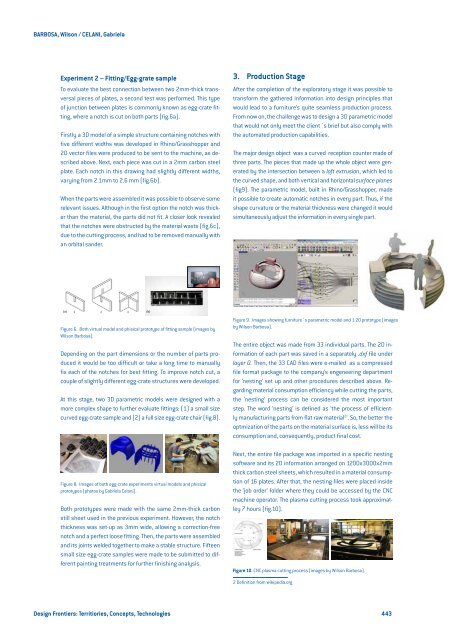
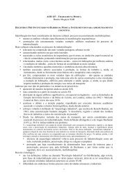
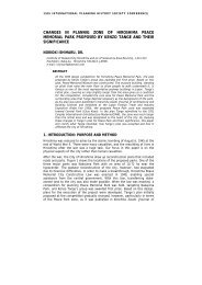
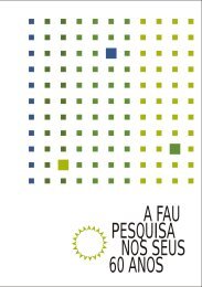
- Page 441: How to go from the file to the fact
- Page 445 and 446: Space, information and cosmology in
- Page 447 and 448: BOECHAT, Marina Pantoja tween ‘ph
- Page 449 and 450: The new imperialism: the internatio
- Page 451 and 452: Frontiers of looking past: a Nietzs
- Page 453 and 454: Frontiers of looking past: a Nietzs
- Page 455 and 456: Design, histories, empires and peri
- Page 457 and 458: Design, histories, empires and peri
- Page 459 and 460: Mythification of national discourse
- Page 461 and 462: Mythification of National Discourse
- Page 463 and 464: Mythification of National Discourse
- Page 465 and 466: Towards a digital batavia: resonanc
- Page 467 and 468: Towards a Digital Batavia: Resonanc
- Page 469 and 470: Questionable translatability: theco
- Page 471 and 472: Questionable translatability: theco
- Page 473 and 474: Eastern craft in Orientalism and Mo
- Page 475 and 476: Eastern craft in Orientalism and Mo
- Page 477 and 478: Mapping Cup & Saucer Design in the
- Page 479 and 480: Mapping Cup & Saucer Design in the
- Page 481 and 482: Mappin tells the history of graphic
- Page 483 and 484: Mappin tells the history of graphic
- Page 485 and 486: Mappin tells the history of graphic
- Page 487 and 488: “Go you too to Amazonia”: analy
- Page 489 and 490: “Go you too to Amazonia”: analy
- Page 491 and 492: Organic Design, MoMA 1940: the brea
- Page 493 and 494:
Organic Design, MoMA 1940: the brea
- Page 495 and 496:
Modern design meets Latin America:
- Page 497 and 498:
Modern design meets Latin America:
- Page 499 and 500:
Lina Bo Bardi and Aloisio Magalhãe
- Page 501 and 502:
Lina Bo Bardi and Aloisio Magalhãe
- Page 503 and 504:
The graphic translation by the desi
- Page 505 and 506:
The Graphic Translation by the Desi
- Page 507 and 508:
The design of Manoel Bandeira: a hi
- Page 509 and 510:
The design of Manoel Bandeira: a hi
- Page 511 and 512:
Open strand Victor Margolin / Chair
- Page 513 and 514:
Brazilian Graphic Design in the ‘
- Page 515 and 516:
Brazilian Graphic Design in the ‘
- Page 517 and 518:
The Design of book bovers in Brazil
- Page 519 and 520:
The Design of book bovers in Brazil
- Page 521 and 522:
The design of Fred Jordan With his
- Page 523 and 524:
The design of Fred Jordan Figure 2.
- Page 525 and 526:
Domestic technologies and moderniza
- Page 527 and 528:
Domestic technologies and moderniza
- Page 529 and 530:
la escuela de Artes y Oficios de sa
- Page 531 and 532:
CAsTillO, eduardo The author(s) of
- Page 533 and 534:
Itineraries for a Design Culture in
- Page 535 and 536:
FARKAS, Mónica / STERLA, Mauricio
- Page 537 and 538:
Sertanejo Art Deco: an inspiration
- Page 539 and 540:
SOUZA, José Marconi B. de / ROSSI,
- Page 541 and 542:
SOUZA, José Marconi B. de / ROSSI,
- Page 543 and 544:
Souza, José Marconi B. de / Rossi,
- Page 545 and 546:
Architectural lettering: from infor
- Page 547 and 548:
Architectural lettering: from infor
- Page 549 and 550:
A dialogue between art and city thr
- Page 551 and 552:
HANNS, Daniela Kutschat / DE MARCHI
- Page 553 and 554:
Vernacular design: a discussion on
- Page 555 and 556:
Vernacular design: A discussion on
- Page 557 and 558:
Italian Radicals and Dutch conceptu
- Page 559 and 560:
Italian Radicals and Dutch Conceptu
- Page 561 and 562:
Italian Radicals and Dutch Conceptu
- Page 563 and 564:
Art criticism and the semantic cons
- Page 565 and 566:
Art criticism and the semantic cons
- Page 567 and 568:
Interieur Kortrijk, an edu-commerci
- Page 569 and 570:
Interieur Kortrijk, an edu-commerci
- Page 571 and 572:
The story of convertible Sofa-Bed:
- Page 573 and 574:
MERZALI CELIKOGLU, Ozge / ER, Alpay
- Page 575 and 576:
MERZALI CELIKOGLU, Ozge / ER, Alpay
- Page 577 and 578:
Vapourware and the agency of ideas
- Page 579 and 580:
Vapourware and the Agency of Ideas
- Page 581 and 582:
Pre-Columbian Asceticism: the Tuza-
- Page 583 and 584:
Pre-Columbian Asceticism. The Tuza-
- Page 585 and 586:
The collection of textbooks “Tape
- Page 587 and 588:
RAMIL, Chris standards for the layo
- Page 589 and 590:
“Their pen draws everything, as i
- Page 591 and 592:
Diniz, Kollontai The author(s) of t
- Page 593 and 594:
Diniz, Kollontai The author(s) of t
- Page 595 and 596:
Cruzeiro Novo Project: Design and t
- Page 597 and 598:
Cruzeiro Novo Project: Design and t
- Page 599 and 600:
Design for a sustainable culture Fi
- Page 601 and 602:
Design for a sustainable culture th
- Page 603 and 604:
Design for a sustainable culture al
- Page 605 and 606:
Design and biodiversity: the produc
- Page 607 and 608:
Design and biodiversity: the produc
- Page 609 and 610:
Lightness and beauty in furniture d
- Page 611 and 612:
Lightness and beauty in furniture d
- Page 613 and 614:
About ICDHS / The International Com
- Page 615 and 616:
Emmanuel Ruffo / Institute for Arch