- Page 2 and 3:
All reasonable steps have been take
- Page 4 and 5:
Instrument Photographic Choice of I
- Page 6 and 7:
iv Contents Chapter 5 - Maintenance
- Page 8 and 9:
The specimen chamber of the Slereos
- Page 10 and 11:
The User Interface Overview The use
- Page 12 and 13:
5. Panel Selection There is one oth
- Page 14 and 15:
B If B is pressed. the arrow keys m
- Page 16 and 17:
The top window, see Figure 1.3, pro
- Page 18 and 19:
Individual items can be selected or
- Page 20 and 21:
1~1~ Chapter 1 Getting Started i '
- Page 22 and 23:
all the operating conditions of the
- Page 24 and 25:
1-20 ~bapter 1 ~g S~ move the mouse
- Page 26 and 27:
FIgUre 1.10 Image of First Peak Set
- Page 28 and 29:
Chapter 2 This chapter contains the
- Page 30 and 31:
Chapter 1. Operation 2--3 " -- Scan
- Page 32 and 33:
Chapter 2. Operation 2.,.,5 ,- . ..
- Page 34 and 35:
, , Chapter 1. ~ - 2-- 7 ""a-uu"" 1
- Page 36 and 37:
1. Admit air to the gun. Open the g
- Page 38 and 39:
Automatic Stage lnitialise The stag
- Page 40 and 41:
For LaB,:- 1 Press the Emission but
- Page 42 and 43:
~I.~ Chapter 2 Operation -'--"=-,'Z
- Page 44 and 45:
2-18 Chapter 1. Operation - - - - a
- Page 46 and 47:
2-20 Chapter 2. Operation. 1 2 t Se
- Page 48 and 49:
2-22 Chapter 1. Operation If the wo
- Page 50 and 51:
2-24 Chapter 2 Operation The Zone T
- Page 52 and 53:
Quad Mode Quad mode is selected fro
- Page 54 and 55:
2-28 Chapter 2 Operation . - -, , "
- Page 56 and 57:
On the histogram display there is a
- Page 58 and 59:
Panels A panel is a special kind of
- Page 60 and 61:
current text string). In addition t
- Page 62 and 63:
Micron Markers Two types of micron
- Page 64 and 65:
Graticule and Crosshairs Graticule
- Page 66 and 67:
HRRU Camera This sets the type of c
- Page 68 and 69:
2..42 Cbapter 1. Operation ~ I It h
- Page 70 and 71:
current when the image was saved. T
- Page 72 and 73:
2-46 Chapter 2 Operation The Clipbo
- Page 74 and 75:
Having now become familiar with the
- Page 76 and 77:
high a probe current, thus the acce
- Page 78 and 79:
, Chapter 3 Advanced Operation 3-5
- Page 80 and 81:
3. The retractable backscattered el
- Page 82 and 83:
I~.." - Chapter 3 Advanced Operatio
- Page 84 and 85:
"".~-I Chapter 3 Advanced Operation
- Page 86 and 87:
" Chapter 3 Advanced Operation 3-13
- Page 88 and 89:
Non-Volatile, Non-Conductors If it
- Page 90 and 91:
The solvent is then allowed to evap
- Page 92 and 93:
Chapter 3 Advanced ~OD 3-19 -c - -
- Page 94 and 95:
Other Menu Features The display of
- Page 96 and 97:
Points and Steps In addition to the
- Page 98 and 99:
Confirm This instruction check that
- Page 100 and 101:
._~ Chapter c" ~ 3 Advanced Operati
- Page 102 and 103:
Remove Removing a macro from a libr
- Page 104 and 105:
The position in the list can be con
- Page 106 and 107:
Install The install option copies t
- Page 108 and 109:
Chapter 3 AdvancedOperati on 3-35 3
- Page 110 and 111:
I I PARAMETER I En"ECT OPTIMUM COMM
- Page 112 and 113:
4.5. Good Housekeeping, i.e. keepin
- Page 114 and 115:
Chapter -. 4 System Management - +3
- Page 116 and 117:
4.1.5. Directory Contents I \nGA i
- Page 118 and 119:
4.3. The User Directory Concept A u
- Page 120 and 121:
I this be reql!i~. File Types, e.g.
- Page 122 and 123:
6-12 Chapter 6 Fault Diagnosis The
- Page 124 and 125:
5-2 Chapter 5 Maintenance 5.1.2. Ai
- Page 126 and 127:
STEEL AND ST ~S STEEL, COPPER AND m
- Page 128 and 129:
5-6 Chapter 5 Maintenance Cleaning
- Page 130 and 131:
Cleaning the Aperture Assembly Vent
- Page 132 and 133:
PC Related Faults PC related proble
- Page 134 and 135:
6-4 Chapter 6 Fault Diagnosis , .".
- Page 136 and 137:
6-6 Chapter 6 Fault Diagnosis The I
- Page 138 and 139:
6-8 Chapter 6 Fault Diagnosis . 4.
- Page 140 and 141:
6-10 Chapter 6 Fault Diagnosis! "I
- Page 142:
This file contains the configuratio
- Page 145 and 146:
Please report the problem. F All..E
- Page 147 and 148:
Stereoscan 440 Operator Manual NVRA
- Page 149 and 150:
6-20 Chapter 6 Fault Diagnosis 4 WW
- Page 151 and 152:
Code numbers greater than 40 indica
- Page 153 and 154:
WINDOWSTM APPUCA nON ERROR When a W
- Page 155 and 156:
Introduction As new Window~ applica
- Page 157 and 158:
Appendix ~ The Stereoscan 440 PC! A
- Page 159 and 160:
" c., Appeudb C Expansion via the P
- Page 161 and 162:
Appendix D Reporting software probl
- Page 163 and 164:
Service Manager - SEM Harry M azal
- Page 165 and 166:
B-2 Appendix E Options- . Operation
- Page 167 and 168:
Controls Angular Measurement The an
- Page 169 and 170:
Angular Measurement Each measuremen
- Page 171 and 172:
The position of the box can be adju
- Page 173 and 174:
I Set the magnification to the requ
- Page 175 and 176:
Positioning the Poin~ In Move mode
- Page 177 and 178:
&14 Appendix E Options I II Image D
- Page 179 and 180:
~ AMaxB This function freezes the i
- Page 181 and 182:
Histogram Equalisation The histogra
- Page 183 and 184:
Overview The input LUT is used to p
- Page 185 and 186:
E-22 Appendix E Options Sawtooth Th
- Page 187 and 188:
A group box at the top left of the
- Page 189 and 190:
" The communication port used by th
- Page 191 and 192:
Selection I The signal mixing panel
- Page 193 and 194: E- 30 Appendix E Options Select one
- Page 195 and 196: E-32 Appendix E Qptions . . High Us
- Page 197 and 198: . The stage Move window comprises a
- Page 199 and 200: Keyboard Control The cursor (arrow)
- Page 201 and 202: E-38 Ap~ ~ Options In addition Macr
- Page 203 and 204: Grainl Grain2 actionedl I To indica
- Page 205 and 206: The function is provided as part of
- Page 207 and 208: Operation Selection Operation of th
- Page 209 and 210: Stage Scan Invalid This indicates i
- Page 211 and 212: E-48 Appendix E Options ~-",,-;,,~_
- Page 213 and 214: Freeze This function will freeze th
- Page 215 and 216: 1.21 Trackerbal/ Introduction This
- Page 217 and 218: Controls Display the pop up control
- Page 219 and 220: Operation Configuration XRay Interf
- Page 221 and 222: E-58 Appendix E Options 11_- X Ray
- Page 223 and 224: Intensity Dot Map Set Up In dot map
- Page 225 and 226: The Linescan data is displayed in a
- Page 227 and 228: E-64 AppeDdjx E ~oos ... ~~ full sc
- Page 229 and 230: Annotation A set of annotation labe
- Page 231 and 232: 2. 2.1 Stage Motorisation The stage
- Page 233 and 234: Camera Image Select between Live, S
- Page 235 and 236: If the box marked Fast is selected,
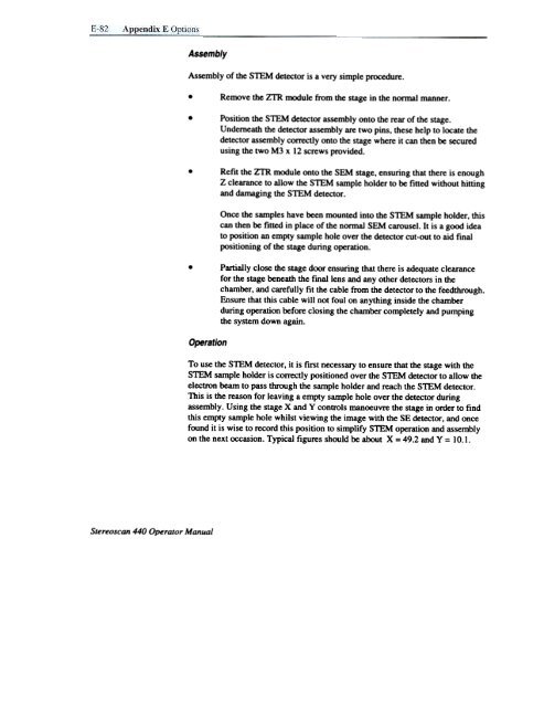
- Page 237 and 238: Remove the Camera assembly from the
- Page 239 and 240: ~--~- ~- , -~~::~ '#:r: .TungsIen F
- Page 241 and 242: .,, , or_~ :---1 ' ' --~... 'FG'-~-
- Page 243: Figures 9,10,11,12 Emission Images
- Page 247 and 248: 4. Select SCM Image from the Specim
- Page 249 and 250: ~ ~ ~ ~ E I I I I I I Stereoscan 44
- Page 251 and 252: DOS, 4-1 Dose rate, 3-12 Dual magni
- Page 253 and 254: 1-4 Index Rotary pump Oil. 5-2 Oil
- Page 255: Appendices s+Shift ff ~ I ARRO~ ~ys


