

Agilent 34970A/34972A Data Acquisition / Switch Unit
Agilent 34970A/34972A Data Acquisition / Switch Unit
Agilent 34970A/34972A Data Acquisition / Switch Unit

Create successful ePaper yourself
Turn your PDF publications into a flip-book with our unique Google optimized e-Paper software.
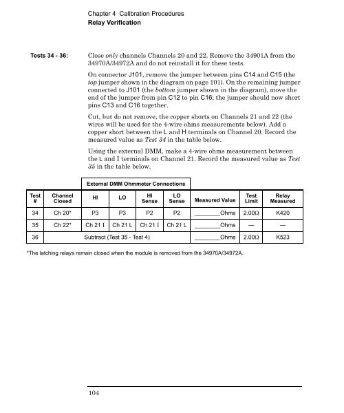
Chapter 4 Calibration Procedures<br />
Relay Verification<br />
Tests 34 - 36:<br />
Close only channels Channels 20 and 22. Remove the 34901A from the<br />
<strong>34970A</strong>/<strong>34972A</strong> and do not reinstall it for these tests.<br />
On connector J101, remove the jumper between pins C14 and C15 (the<br />
top jumper shown in the diagram on page 101). On the remaining jumper<br />
connected to J101 (the bottom jumper shown in the diagram), move the<br />
end of the jumper from pin C12 to pin C16; the jumper should now short<br />
pins C13 and C16 together.<br />
Cut, but do not remove, the copper shorts on Channels 21 and 22 (the<br />
wires will be used for the 4-wire ohms measurements below). Add a<br />
copper short between the L and H terminals on Channel 20. Record the<br />
measured value as Test 34 in the table below.<br />
Using the external DMM, make a 4-wire ohms measurement between<br />
the L and I terminals on Channel 21. Record the measured value as Test<br />
35 in the table below.<br />
External DMM Ohmmeter Connections<br />
Test<br />
#<br />
Channel<br />
Closed<br />
HI LO HI<br />
Sense<br />
LO<br />
Sense<br />
Measured Value<br />
Test<br />
Limit<br />
Relay<br />
Measured<br />
34 Ch 20* P3 P3 P2 P2 ________Ohms 2.00 K420<br />
35 Ch 22* Ch 21 I Ch 21 L Ch 21 I Ch 21 L ________Ohms — —<br />
36 Subtract (Test 35 - Test 4) ________Ohms 2.00 K523<br />
*The latching relays remain closed when the module is removed from the <strong>34970A</strong>/<strong>34972A</strong>.<br />
104


