

Agilent 34970A/34972A Data Acquisition / Switch Unit
Agilent 34970A/34972A Data Acquisition / Switch Unit
Agilent 34970A/34972A Data Acquisition / Switch Unit

You also want an ePaper? Increase the reach of your titles
YUMPU automatically turns print PDFs into web optimized ePapers that Google loves.
Chapter 5 Theory of Operation<br />
Internal DMM<br />
Input Amplifier<br />
Unless otherwise noted, components in this discussion are located on the<br />
A4 circuit assembly (34970-66504).<br />
The DC Amplifier circuit is used by every measuring function except<br />
frequency and period. Analog switch U101B selects various input signals<br />
for measurement by the ADC. <strong>Switch</strong> U101B has three sources which<br />
can be dynamically selected: measure customer input (MC), measure zero<br />
input (MZ), and precharge (PRE). The MC state is the actual input 4<br />
measurement. The MZ state measures internal offset voltages which are<br />
also present in the MC measurement. The final measurement result is<br />
computed from MC–MZ. The PRE state is used to “precharge” internal<br />
capacitances to reduce charge injection to the input terminal from the<br />
dynamic switching of MC and MZ. Autozero off disables the dynamic<br />
switching of the amplifier input. However, a new MZ value is<br />
automatically taken whenever a new function or range is selected, even<br />
if autozero is turned off.<br />
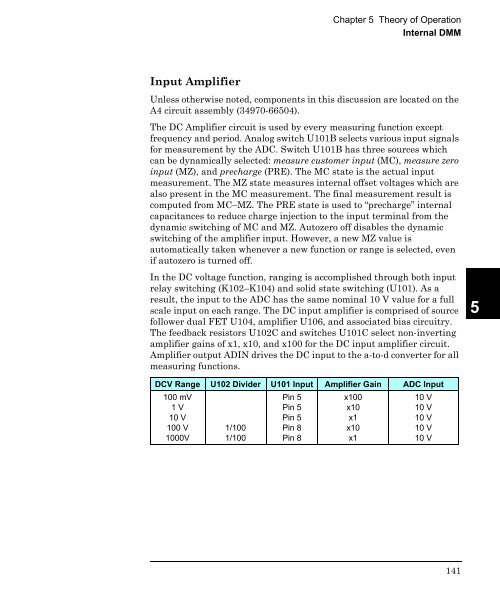
In the DC voltage function, ranging is accomplished through both input<br />
relay switching (K102–K104) and solid state switching (U101). As a<br />
result, the input to the ADC has the same nominal 10 V value for a full<br />
scale input on each range. The DC input amplifier is comprised of source<br />
follower dual FET U104, amplifier U106, and associated bias circuitry.<br />
The feedback resistors U102C and switches U101C select non-inverting<br />
amplifier gains of x1, x10, and x100 for the DC input amplifier circuit.<br />
Amplifier output ADIN drives the DC input to the a-to-d converter for all<br />
measuring functions.<br />
5<br />
DCV Range U102 Divider U101 Input Amplifier Gain ADC Input<br />
100 mV<br />
1 V<br />
10 V<br />
100 V<br />
1000V<br />
1/100<br />
1/100<br />
Pin 5<br />
Pin 5<br />
Pin 5<br />
Pin 8<br />
Pin 8<br />
x100<br />
x10<br />
x1<br />
x10<br />
x1<br />
10 V<br />
10 V<br />
10 V<br />
10 V<br />
10 V<br />
141


