

Agilent 34970A/34972A Data Acquisition / Switch Unit
Agilent 34970A/34972A Data Acquisition / Switch Unit
Agilent 34970A/34972A Data Acquisition / Switch Unit

Create successful ePaper yourself
Turn your PDF publications into a flip-book with our unique Google optimized e-Paper software.
Chapter 5 Theory of Operation<br />
Multifunction Module<br />
Totalizer<br />
Components in this discussion are located on the A1 circuit assembly<br />
(34907-66501).<br />
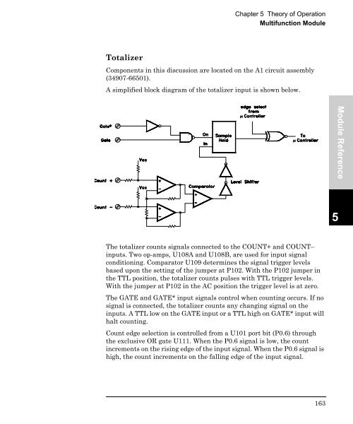
A simplified block diagram of the totalizer input is shown below.<br />
Module Reference<br />
5<br />
The totalizer counts signals connected to the COUNT+ and COUNT–<br />
inputs. Two op-amps, U108A and U108B, are used for input signal<br />
conditioning. Comparator U109 determines the signal trigger levels<br />
based upon the setting of the jumper at P102. With the P102 jumper in<br />
the TTL position, the totalizer counts pulses with TTL trigger levels.<br />
With the jumper at P102 in the AC position the trigger level is at zero.<br />
The GATE and GATE* input signals control when counting occurs. If no<br />
signal is connected, the totalizer counts any changing signal on the<br />
inputs. A TTL low on the GATE input or a TTL high on GATE* input will<br />
halt counting.<br />
Count edge selection is controlled from a U101 port bit (P0.6) through<br />
the exclusive OR gate U111. When the P0.6 signal is low, the count<br />
increments on the rising edge of the input signal. When the P0.6 signal is<br />
high, the count increments on the falling edge of the input signal.<br />
163


