- Page 1 and 2:
Compressors 485 Vertical V-type W-t
- Page 3 and 4:
For a reciprocating piston compress
- Page 5 and 6:
Compressors 489 top of the vanes sl
- Page 7 and 8:
Compressors 491 portion of the rota
- Page 9 and 10:
Compressors 493 Summary of Rotary C
- Page 11 and 12:
References 495 Figure 3-83. Multist
- Page 13 and 14:
Drilling and Well Completions Frede
- Page 15 and 16:
- Drilling and Well Completions DER
- Page 17 and 18:
Derricks and Portable Masts 501 Guy
- Page 19 and 20:
Derricks and Portable Masts 503 c I
- Page 21 and 22:
~~ ~ Nominal Base Square Two I" or
- Page 23 and 24:
Derricks and Portable Masts 507 The
- Page 25 and 26:
Derricks and Portable Masts 509 c.
- Page 27 and 28:
Design Specifications Derricks and
- Page 29 and 30:
Derricks and Portable Masts 513 Whe
- Page 31 and 32:
Derricks and Portable Masts 515 to
- Page 33 and 34:
Derricks and Portable Masts 517 1.
- Page 35 and 36:
Derricks and Portable Masts 519 All
- Page 37 and 38:
Derricks and Portable Masts 541 and
- Page 39 and 40:
Hoisting System 543 75, 562.50 lb,
- Page 41 and 42:
600,000 9, Hoisting System 525 bloc
- Page 43 and 44:
Hoisting System 527 Power output lo
- Page 45 and 46:
Hoisting System 529 Transmission an
- Page 47 and 48:
Hoisting System 531 16. Tension mem
- Page 49 and 50:
Hoisting System 533 0 too 150 250 3
- Page 51 and 52:
Hoisting System 535 where SF, = yie
- Page 53 and 54:
Hoisting System 537 Table 4-6 (cont
- Page 55 and 56:
\-I-/ 15" 15" \-I?/ Hoisting System
- Page 57 and 58:
Hoisting System 541 Figure 4-16. Tr
- Page 59 and 60:
Hoisting System 543 loads are unexp
- Page 61 and 62:
Hoisting System 545 Wear and crocks
- Page 63 and 64:
Hoisting System 547 ,-Wear and crac
- Page 65 and 66:
Hoisting System 549 Weor of pins an
- Page 67 and 68:
Hoisting System 551 Wear and crocks
- Page 69 and 70:
Hoisting System 553 INSPECTION: Hea
- Page 71 and 72:
Table 4-9 (continued) Hoisting Syst
- Page 73 and 74:
Table 4-9 (continued) Hoisting Syst
- Page 75 and 76:
Hoisting System 559 Table 4-10 (con
- Page 77 and 78:
Hoisting System 561 0.145 3.68 3,32
- Page 79 and 80:
Hoisting System 563 0.230 0.231 0.2
- Page 81 and 82:
Hoisting System 565 The purchaser m
- Page 83 and 84:
Table 4-14 Classification Wire Rope
- Page 85 and 86:
Hoisting System 569 Table 4-18 6x37
- Page 87 and 88:
Table 4-23 6x25 “B,” 6x27 “H,
- Page 89 and 90:
Hoisting System 573 FIGhE4.44 FIGUR
- Page 91 and 92:
Hoisting System 575 (text conlznued
- Page 93 and 94:
Table 4-24 Wire Diameter Tolerance
- Page 95 and 96:
Hoisting System 579 M Figure 4-66.
- Page 97 and 98:
Hoisting System 581 Table 4-28 Requ
- Page 99 and 100:
Hoisting System 583 Table 4-30 Typi
- Page 101 and 102:
Hoisting System 585 Minimum Design
- Page 103 and 104:
y CASE "0" s-3 Drum Hoisting System
- Page 105 and 106:
Hoisting System 589 Figure 4-71A sh
- Page 107 and 108:
Hoisting System 591 a. The seizing
- Page 109 and 110:
Hoisting System 593 This solution i
- Page 111 and 112:
~ ~~~ Hoisting System 595 Attachmen
- Page 113 and 114:
Hoisting System 597 Vee Side of Der
- Page 115 and 116:
Hoisting System 599 spooling condit
- Page 117 and 118:
Hoisting System 601 Grooves for san
- Page 119 and 120:
Hoisting System 603 WEIGHT OF FLUID
- Page 121 and 122:
Hoisting System 605 20 I I I 1 I I
- Page 124 and 125:
608 Drilling and Well Completions B
- Page 126 and 127:
610 Drilling and Well Completions S
- Page 128 and 129:
612 Drilling and Well Completions 4
- Page 130 and 131:
614 Drilling and Well Completions n
- Page 132 and 133:
616 Drilling and Well Completions W
- Page 134 and 135:
618 Drilling and Well Completions S
- Page 136 and 137:
620 Drilling and Well Completions F
- Page 138 and 139:
622 Drilling and Well Completions -
- Page 140 and 141:
624 Drilling and Well Completions F
- Page 142 and 143:
626 Drilling and Well Completions 1
- Page 144 and 145:
628 Drilling and Well Completions F
- Page 146 and 147:
630 Drilling and Well Completions s
- Page 148 and 149:
Table 4-38 Mud Pump Performance-Dup
- Page 150:
NAWfACNWR COWIINEWAL EYSCO(DVPLOO T
- Page 154 and 155:
Table 4-38 (continued) Q, w 00 5 a
- Page 158 and 159:
642 Drilling and Well Completions T
- Page 160 and 161:
644 Drilling and Well Completions (
- Page 162 and 163:
646 Drilling and Well Completions .
- Page 164 and 165:
1."y SZ'Z# 8/1-02 01 ncf, VIE-02 0)
- Page 166 and 167:
650 Drilling and Well Completions F
- Page 168 and 169:
652 Drilling and Well Completions T
- Page 170 and 171:
654 Drilling and Well Completions R
- Page 172 and 173:
656 Drilling and Well Completions R
- Page 174:
658 Drilling and Well Completions F
- Page 177 and 178:
Drilling Muds and Completion Fluids
- Page 179 and 180:
Drilling Muds and Completion Fluids
- Page 181 and 182:
Drilling Muds and Completion Fluids
- Page 183 and 184:
Drilling Muds and Completion Fluids
- Page 185 and 186:
Drilling Muds and Completion Fluids
- Page 187 and 188:
Drilling Muds and Completion Fluids
- Page 189 and 190:
Drilling Muds and Completion Fluids
- Page 191 and 192:
Drilling Muds and Completion Fluids
- Page 193 and 194:
80 Drilling Muds and Completion Flu
- Page 195 and 196:
Drilling Muds and Completion Fluids
- Page 197 and 198:
Drilling Muds and Completion Fluids
- Page 199 and 200:
Drilling Muds and Completion Fluids
- Page 201 and 202:
Drilling Muds and Completion Fluids
- Page 203 and 204:
Drilling Muds and Completion Fluids
- Page 205 and 206:
Drilling Muds and Completion Fluids
- Page 207 and 208:
Drilling Muds and Completion Fluids
- Page 209 and 210:
Drilling Muds and Completion Fluids
- Page 211 and 212:
Drilling Muds and Completion Fluids
- Page 213 and 214:
Drilling Muds and Completion Fluids
- Page 215 and 216:
Drilling Muds and Completion Fluids
- Page 217 and 218:
Drilling Muds and Completion Fluids
- Page 219 and 220:
~ ~~ Drilling Muds and Completion F
- Page 221 and 222:
Drilling Muds and Completion Fluids
- Page 223 and 224:
Drilling Muds and Completion Fluids
- Page 225 and 226:
~~ ~ ~ ~ ~~ ~ Drilling Muds and Com
- Page 227 and 228:
Drilling Muds and Completion Fluids
- Page 229 and 230:
Drilling Muds and Completion Fluids
- Page 231 and 232:
Drill String: Composition and Desig
- Page 233 and 234:
Drill String: Composition and Desig
- Page 235 and 236:
Drill String: Composition and Desig
- Page 237 and 238:
where DF = W= Wd‘ = %= K, = r, =
- Page 239 and 240:
Drill String: Composition and Desig
- Page 241 and 242:
Drill String: Composition and Desig
- Page 243 and 244:
Drill String: Composition and Desig
- Page 245 and 246:
Drill String: Composition and Desig
- Page 247 and 248:
Drill String: Composition and Desig
- Page 249 and 250:
Drill String: Composition and Desig
- Page 251 and 252:
Drill String: Composition and Desig
- Page 253 and 254:
Drill String: Composition and Desig
- Page 255 and 256:
Drill String: Composition and Desig
- Page 257 and 258:
Table 4-81 Premium (Used) Drill Pip
- Page 259 and 260:
Table 4-83 Class 3 (Used) Drill Pip
- Page 261 and 262:
Drill String: Composition and Desig
- Page 263 and 264:
Drill String: Composition and Desig
- Page 265 and 266:
Drill String: Composition and Desig
- Page 267 and 268:
~ -- --- Drill String: Composition
- Page 269 and 270:
6.85 9.50 Table 4-86 Selection Char
- Page 271 and 272:
In In t- ." B v1 a" c 0 ." .3 Y 8 2
- Page 273 and 274:
Drill String: Composition and Desig
- Page 275 and 276:
~ . Drill String: Composition and D
- Page 277 and 278:
Drill String: Composition and Desig
- Page 279 and 280:
Drill String: Composition and Desig
- Page 281 and 282:
Drill String: Composition and Desig
- Page 283 and 284:
Drill String: Composition and Desig
- Page 285 and 286:
Drilling Bits and Downhole Tools 76
- Page 287 and 288:
~ ~~ ~~ ~ ~ ~ ~ ~~ ~~~~ Drilling Bi
- Page 289 and 290:
Drilling Bits and Downhole Tools 77
- Page 291 and 292:
Drilling Bits and Downhole Tools 77
- Page 293 and 294:
Drilling Bits and Downhole Tools 77
- Page 295 and 296:
Drilling Bits and Downhole Tools 77
- Page 297 and 298:
Drilling Bits and Downhole Tools 78
- Page 299 and 300:
Drilling Bits and Downhole Tools 78
- Page 301 and 302:
Drilling Bits and Downhole Tools 78
- Page 303 and 304:
The bit hydraulic horsepower HP, is
- Page 305 and 306:
Drilling Bits and Downhole Tools 78
- Page 307 and 308:
Drilling Bits and Downhole Tools 79
- Page 309 and 310:
Drilling Bits and Downhole Tools 79
- Page 311 and 312:
Weight on Bit and Rotary Speed for
- Page 313 and 314:
Drilling Bits and Downhole Tools 79
- Page 315 and 316:
Drilling Bits and Downhole Tools 79
- Page 317 and 318:
Drilling Bits and Downhole Tools 80
- Page 319 and 320:
Drilling Bits and Downhole Tools 80
- Page 321 and 322:
~ OPEN Drilling Bits and Downhole T
- Page 323 and 324:
Drilling Bits and Downhole Tools 80
- Page 325 and 326:
Drilling Bits and Downhole Tools 80
- Page 327 and 328:
Drilling Bits and Downhole Tools 81
- Page 329 and 330:
Drilling Bits and Downhole Tools 81
- Page 331 and 332:
Drilling Bits and Downhole Tools 81
- Page 333 and 334:
Drilling Bits and Downhole Tools 81
- Page 335 and 336:
Drilling Bits and Downhole Tools 81
- Page 337 and 338:
Drilling Bits and Downhole Tools 82
- Page 339 and 340:
Drilling Bits and Downhole Tools 82
- Page 341 and 342:
Drilling Bits and Downhole Tools 82
- Page 343 and 344:
Drilling Bits and Downhole Tools 82
- Page 345 and 346:
DRILLING MUD HYDRAULICS Drilling Mu
- Page 347 and 348:
Drilling Mud Hydraulics 83 1 where
- Page 349 and 350:
Drilling Mud Hydraulics 833 The ave
- Page 351 and 352:
Drilling Mud Hydraulics 835 words,
- Page 353 and 354:
Drilling Mud Hydraulics 837 In the
- Page 355 and 356:
AP5 = [ 0.729 (2.4)(118.62) (2)(0.7
- Page 357 and 358:
Air and Gas Drilling 841 Air and Ga
- Page 359 and 360:
~ ~ ~ Air and Gas Drilling 843 Air
- Page 361 and 362:
Air and Gas Drilling 845 The booste
- Page 363 and 364:
Air and Gas Drilling 847 Drill Pipe
- Page 365 and 366:
Air and Gas Drilling 849 above the
- Page 367 and 368:
Air and Gas Drilling 851 [-a Rotati
- Page 369 and 370:
Air and Gas Drilling 853 drilling,
- Page 371 and 372:
Air and Gas Drilling 855 Table 4-10
- Page 373 and 374:
Air and Gas Drilling 857 Knowing th
- Page 375 and 376:
Air and Gas Drilling 859 From Equat
- Page 377 and 378:
Air and Gas Drilling 861 log,,p,,,
- Page 379 and 380:
Downhole Motors 863 In the late 195
- Page 381 and 382:
Downhole Motors 865 Figure 4-191. D
- Page 383 and 384:
Downhole Motors 867 Circulation Rat
- Page 385 and 386:
Downhole Motors 869 Stator t Figure
- Page 387 and 388:
Table 4-111 Turbine Motor, 6%-in. O
- Page 389 and 390:
HP, = 217( -) 1421 2842 Downhole Mo
- Page 391 and 392:
Downhole Motors 875 Similarly, the
- Page 393 and 394:
Downhole Motors 877 8000 pall = 458
- Page 395 and 396:
pal, = 3825 psi qal, = 340 gpm Down
- Page 397 and 398:
p, = 3236 psi Downhole Motors 881 8
- Page 399 and 400: Downhole Motors 883 Flow Figure 4-2
- Page 401 and 402: Downhole Motors 885 stator is made
- Page 403 and 404: Downhole Motors 887 operating speed
- Page 405 and 406: ~~ ~ ~ Downhole Motors 889 - 9*P,a%
- Page 407 and 408: Downhole Motors 891 2800 2400 2200
- Page 409 and 410: Downhole Motors 893 OFF BOllOM BEAR
- Page 411 and 412: Downhole Motors 895 3000 .- n v) a
- Page 413 and 414: Downhole Motors 897 t? v) p,= 1382
- Page 415 and 416: Downhole Motors 899 The hydraulic e
- Page 417 and 418: MWD and LWD 901 successfully in man
- Page 419 and 420: MWD and LWD 903 Naturally for opera
- Page 421 and 422: MWD and LWD 905 MAGNETOMETER " \ Y'
- Page 423 and 424: MWD and LWD 907 Coils Po Figure 4-2
- Page 425 and 426: MWD and LWD 909 continuous componen
- Page 427 and 428: MWD and LWD 911 The gravity tool fa
- Page 429 and 430: g MWD and LWD 913 A \ DRIVE WINDING
- Page 431 and 432: MWD and LWD 915 Figure 4-230. Photo
- Page 433 and 434: Table 4-119 Accelerometer Output fo
- Page 435 and 436: MWD and LWD 919 Also needed: Vector
- Page 437 and 438: MWD and LWD 921 Using the drawing F
- Page 439 and 440: MWD and LWD 923 where x = elongatio
- Page 441 and 442: MWD and LWD 925 where m is the dece
- Page 443 and 444: MWD and LWD 927 - Housing c Sensor
- Page 445 and 446: MWD and LWD 929 Pressure Pick-up Fi
- Page 447 and 448: MWD and LWD 931 The cone can be rep
- Page 449: MWD and LWD 933 for measuring the d
- Page 453 and 454: MWD and LWD 937 The early system wa
- Page 455 and 456: MWD and LWD 939 Retrievable Tools.
- Page 457 and 458: MWD and LWD 941 where P(x) = pressu
- Page 459 and 460: Demonstration, Transmit a range of
- Page 461 and 462: ~~~ MWD and LWD 945 2. What is the
- Page 463 and 464: ~ 2. S-23-E = 157" Default: 0110111
- Page 465 and 466: MWD and LWD 949 Pressure (psi) 0 20
- Page 467 and 468: MWD and LWD 951 x = distance in ft
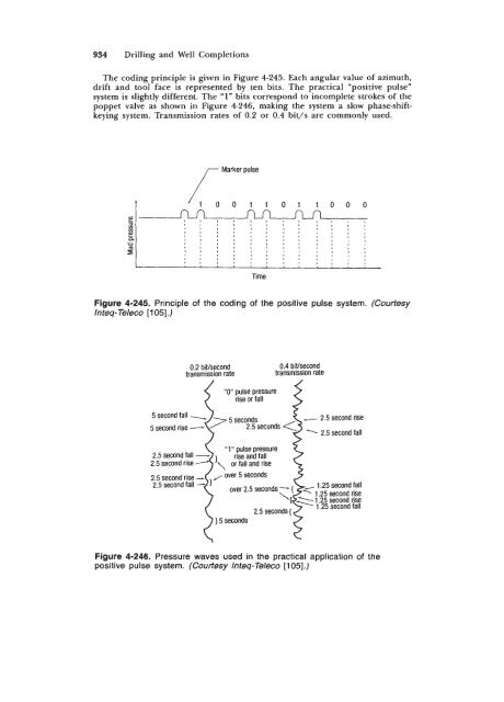
- Page 469 and 470: MWD and LWD 953 Solution 1. a. 6,25
- Page 471 and 472: MWD and LWD 955 M - J H Figure 4-25
- Page 473 and 474: MWD and LWD 957 FOIL GRID PATTERN T
- Page 475 and 476: MWD and LWD 959 I I I p *:::!i I I
- Page 477 and 478: MWD and LWD 961 One steel diaphragm
- Page 479 and 480: MWD and LWD 963 Temperature sensor
- Page 481 and 482: MWD and LWD 965 (4-200) where Rgem
- Page 483 and 484: MWD and LWD 967 Gage response to ax
- Page 485 and 486: MWD and LWD 969 (4-203) (4-204) Sol
- Page 487 and 488: MWD and LWD 971 Hydrostatic pressur
- Page 489 and 490: MWD and LWD 973 Figure 4-269. Examp
- Page 491 and 492: MWD and LWD 975 Flgure 4-271. MWD f
- Page 493 and 494: MWD and LWD 977 3. electromagnetic
- Page 495 and 496: MWD and LWD 979 The system is simil
- Page 497 and 498: MWD and LWD 981 Figure 4-276. Compa
- Page 499 and 500: MWD and LWD 983 DUAL INDUCTION-LL3