F4200N Manual - Fisnar.fr
F4200N Manual - Fisnar.fr
F4200N Manual - Fisnar.fr

You also want an ePaper? Increase the reach of your titles
YUMPU automatically turns print PDFs into web optimized ePapers that Google loves.
<strong>F4200N</strong> Operating <strong>Manual</strong><br />
Section 7: Error Messages and Specifications<br />
Part # 562187N<br />
Rev. C Jun 2011<br />
IMPORTANT NOTES:<br />
1. Output signals should be used only to drive external relays. Do not power external<br />
devices directly through output signals. Electrical noise will damage the output<br />
signal relay.<br />
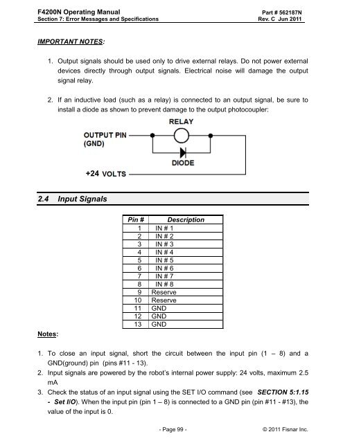
2. If an inductive load (such as a relay) is connected to an output signal, be sure to<br />
install a diode as shown to prevent damage to the output photocoupler:<br />
+24<br />
2.4 Input Signals<br />
Notes:<br />
Pin # Description<br />
1 IN # 1<br />
2 IN # 2<br />
3 IN # 3<br />
4 IN # 4<br />
5 IN # 5<br />
6 IN # 6<br />
7 IN # 7<br />
8 IN # 8<br />
9 Reserve<br />
10 Reserve<br />
11 GND<br />
12 GND<br />
13 GND<br />
1. To close an input signal, short the circuit between the input pin (1 – 8) and a<br />
GND(ground) pin (pins #11 - 13).<br />
2. Input signals are powered by the robot‟s internal power supply: 24 volts, maximum 2.5<br />
mA<br />
3. Check the status of an input signal using the SET I/O command (see SECTION 5:1.15<br />
- Set I/O). When the input pin (pin 1 – 8) is connected to a GND pin (pin #11 - #13), the<br />
value of the input is 0.<br />
- Page 99 - © 2011 <strong>Fisnar</strong> Inc.