- Page 1 and 2:
ICS-1000 ION CHROMATOGRAPHY SYSTEMO
- Page 3 and 4:
Contents1 • Introduction1.1 Intro
- Page 6 and 7:
ICS-1000 Ion Chromatography System4
- Page 8 and 9:
ICS-1000 Ion Chromatography SystemB
- Page 10 and 11:
ICS-1000 Ion Chromatography SystemE
- Page 12 and 13:
ICS-1000 Ion Chromatography SystemA
- Page 14 and 15:
ICS-1000 Ion Chromatography System1
- Page 16 and 17:
ICS-1000 Ion Chromatography System1
- Page 18 and 19:
ICS-1000 Ion Chromatography System1
- Page 20 and 21:
ICS-1000 Ion Chromatography SystemI
- Page 22 and 23:
ICS-1000 Ion Chromatography System2
- Page 24 and 25:
ICS-1000 Ion Chromatography SystemS
- Page 26 and 27:
ICS-1000 Ion Chromatography SystemT
- Page 28 and 29:
ICS-1000 Ion Chromatography System
- Page 31 and 32:
2 • Features2.3.2 The ICS-1000 Co
- Page 33 and 34:
2 • FeaturesSystem Controls Overv
- Page 35 and 36:
2 • FeaturesInject ValveDisplays
- Page 37 and 38:
2 • Features2.4 System Component
- Page 39 and 40:
2 • Features2.4.2 Eluent ValveThe
- Page 41 and 42:
2 • FeaturesPressure TransducerFl
- Page 43 and 44:
2 • Featuressample loops in vario
- Page 45 and 46:
2 • Features2.4.6 SuppressorThe s
- Page 47 and 48:
3 • Operation and MaintenanceThis
- Page 49 and 50:
3 • Operation and Maintenance3.2
- Page 51 and 52:
3 • Operation and Maintenance3. I
- Page 53 and 54:
3 • Operation and Maintenance•
- Page 55 and 56:
3 • Operation and Maintenance3.5
- Page 57 and 58:
3 • Operation and Maintenance3.8
- Page 59 and 60:
3 • Operation and Maintenance3.9.
- Page 61 and 62:
3 • Operation and Maintenancestan
- Page 63 and 64:
3 • Operation and Maintenance3.10
- Page 65 and 66:
3 • Operation and Maintenancenew
- Page 67 and 68:
3 • Operation and Maintenance3.12
- Page 69 and 70:
4 • TroubleshootingThis chapter i
- Page 71 and 72:
4 • Troubleshooting4.1 Alarms and
- Page 73 and 74:
4 • TroubleshootingLOAD/INJECT VA
- Page 75 and 76:
4 • TroubleshootingPUMP UNDER PRE
- Page 77 and 78:
4 • TroubleshootingSUPPRESSOR STO
- Page 79 and 80:
4 • TroubleshootingMake sure the
- Page 81 and 82:
4 • Troubleshooting• Blockages
- Page 83 and 84:
4 • Troubleshooting4.6 Erratic Fl
- Page 85 and 86:
4 • Troubleshooting• Malfunctio
- Page 87 and 88:
4 • Troubleshooting• Cell out o
- Page 89 and 90:
4 • Troubleshootingb. Under Insta
- Page 91 and 92:
5•ServiceThis chapter describes I
- Page 93 and 94:
5•ServiceUse the Wellness Panel t
- Page 95 and 96:
5•ServiceAfter calibration, the c
- Page 97 and 98:
5•Service5.1.4 Calibrating the Va
- Page 99 and 100:
5•Service5.3 Replacing Tubing and
- Page 101 and 102:
5•Service5.5 Cleaning and Replaci
- Page 103 and 104:
5•Service5.6 Replacing a Pump Pis
- Page 105 and 106:
5•Service6. The piston does not c
- Page 107 and 108:
5•ServiceReinstalling the Head an
- Page 109 and 110:
5•ServiceValve KnobO-Ring(P/N 055
- Page 111 and 112:
5•Service5. Slide the new cell as
- Page 113 and 114:
5•Service11. Align the top of the
- Page 115 and 116:
5•Service9. Enter the column heat
- Page 117 and 118:
5•Service6. Pull the valve straig
- Page 119 and 120:
5•Service5.15 Priming with Isopro
- Page 121 and 122:
A • SpecificationsA.1 ElectricalM
- Page 123 and 124:
A • SpecificationsA.6 DetectorRan
- Page 125 and 126:
B • InstallationThis chapter prov
- Page 127 and 128:
Unpacking the ICS-1000 System3. Rem
- Page 129 and 130: Installing ChromeleonB.3 Installing
- Page 131 and 132: Installing the Chromeleon Software
- Page 133 and 134: Connecting the ICS-1000 to the Chro
- Page 135 and 136: Connecting the Power CordB.6 Connec
- Page 137 and 138: Setting Up ChromeleonB.8 Setting Up
- Page 139 and 140: Setting Up Chromeleon10. Click the
- Page 141 and 142: Setting Up Chromeleon2. Select the
- Page 143 and 144: Installing and Plumbing the Columns
- Page 145 and 146: Installing and Plumbing the Columns
- Page 147 and 148: Connecting the Waste LinesB.10 Conn
- Page 149 and 150: Setting Up the Eluent ReservoirVERS
- Page 151 and 152: Setting Up a Chromeleon Application
- Page 153 and 154: Setting Up a Chromeleon Application
- Page 155 and 156: Setting Up a Chromeleon Application
- Page 157 and 158: Setting Up a Chromeleon Application
- Page 159 and 160: Setting the Eluent LevelNOTEIf the
- Page 161 and 162: Priming the Pump3. Open the priming
- Page 163 and 164: Equilibrating the SystemB.15 Equili
- Page 165 and 166: Connecting an AS50 Autosampler (Opt
- Page 167 and 168: Connecting an AS50 Autosampler (Opt
- Page 169 and 170: Connecting an AS40 Automated Sample
- Page 171 and 172: Pressurizing the Eluent Reservoir (
- Page 173 and 174: Pump Continuous Seal Wash Connectio
- Page 175 and 176: Manually Connecting to a Control Pa
- Page 177 and 178: Installation TroubleshootingB.23 In
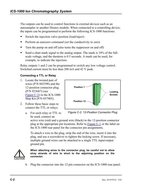
- Page 179: C • TTL and Relay ControlNOTEThe
- Page 183 and 184: C • TTL and Relay Control• Inve
- Page 185 and 186: C • TTL and Relay ControlC.3 Exam
- Page 187 and 188: C • TTL and Relay ControlEnable A
- Page 189 and 190: D • Reordering InformationPart Nu
- Page 191 and 192: E•FAQE.1 How do I hook up an auto
- Page 193 and 194: E•FAQE.12 How do I know when a co
- Page 195 and 196: F • GlossaryAnalytical ColumnSyno
- Page 197 and 198: F • Glossaryof relatively clean s
- Page 199 and 200: F • GlossarySiemens (S)Unit measu
- Page 201 and 202: IndexAAir particulate samples, 3-12
- Page 203 and 204: IndexData rise time, B-46Decibel le
- Page 205 and 206: IndexKKey code (Chromeleon), B-6LLe
- Page 207 and 208: IndexRRear panel, 2-7Analog output
- Page 209 and 210: IndexTTL outputsControlling, C-5Rea