User Manual High Performance AC Drive
User Manual High Performance AC Drive
User Manual High Performance AC Drive
- No tags were found...

You also want an ePaper? Increase the reach of your titles
YUMPU automatically turns print PDFs into web optimized ePapers that Google loves.
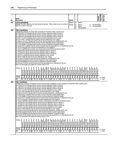
3-48 Programming and ParametersNo.NameDescription331 LstFaultStopModeDisplays the action taken by the drive during the last fault. When a fault occurs, an action istaken as a result of that fault.ValuesDefault:Options:332 700L EventStatusIndicates the presence of certain drive anomalies for PowerFlex 700L (LiquiFlo) drive.Bit 0 [Dsat Phs U1] indicates that the primary structure detected a Dsat on phase U.Bit 1 [Dsat Phs V1] indicates that the primary structure detected a Dsat on phase V.Bit 2 [Dsat Phs W] indicates that the primary structure detected a Dsat on phase W.Bit 3 [Ovr Current1] indicates that the primary structure detected an over current.Bit 4 [Ovr Volt1] - indicates that the primary structure detected an over voltage.Bit 5 [Asym DcLink1] indicates that the primary structure detected an unbalanced DC Link.Bit 6 [Pwr Suply1]indicates that the primary structure detected a power supply failure.Bit 7 [HW Disable1] indicates that the primary structure detected a hardware disable.Bit 8 [Latch Err1] indicates that the primary structure fault was generated but no indicating bit was set.Bit 14 [Cnv NotLogin] the converter was expected but none logged in.Bit 15 [Cnv NotStart] the converter was commanded to start but did not become active.Bit 16 [Dsat Phs U2] the second structure detected a Dsat on phase U.Bit 17 [Dsat Phs V2] the second structure detected a Dsat on phase V.Bit 18 [Dsat Phs W2] the second structure detected a Dsat on phase W.Bit 19 [Ovr Current2] the second structure detected an over current.Bit 20 [Ovr Volt2] the second structure detected an over voltage.Bit 21 [Asym DcLink2] the second structure detected an unbalanced DC Link.Bit 22 [Pwr Suply2] the second structure detected a power supply failure.Bit 23 [HW Disable2] the second structure detected a hardware disable.Bit 24 [Latch Err2] the second structure fault was generated but no indicating bit was set.Note: This parameter was added for firmware version 2.03.0 =0 =1 =2 =“Ignore”“Ignore”“Alarm”“FltCoastStop”LinkableRead-WriteData Type3 = “Flt RampStop“4 = “FltCurLimStop”OptionsReservedReservedReservedReservedReservedReservedReservedLatch Err2HW Disable2Pwr Suply2Asym DcLink2Ovr Volt2Ovr Current2Dsat Phs W2Dsat Phs V2Dsat Phs U2Cnv NotStartCnv NotLoginReservedReservedReservedReservedReservedLatch Err1HW Disable1Pwr Suply1Asym DcLink1Ovr Volt1Ovr Current1Dsat Phs W1Dsat Phs V1Dsat Phs U1Default 0 0 0 0 0 0 0 0 0 0 0 0 0 0 0 0 0 0 0 0 0 0 0 0 0 0 0 0 0 0 0 0Bit 31 30 29 28 27 26 25 24 23 22 21 20 19 18 17 16 15 14 13 12 11 10 9 8 7 6 5 4 3 2 1 0333 700L FaultStatusIndicates the occurrence of exception events that have been configured as fault conditions for PowerFlex 700L (LiquiFlo) drive.Bit 0 [Dsat Phs U1] indicates that the primary structure detected a Dsat on phase U.Bit 1 [Dsat Phs V1] indicates that the primary structure detected a Dsat on phase V.Bit 2 [Dsat Phs W] indicates that the primary structure detected a Dsat on phase W.Bit 3 [Ovr Current1] indicates that the primary structure detected an over current.Bit 4 [Ovr Volt1] indicates that the primary structure detected an over voltage.Bit 5 [Asym DcLink1] indicates that the primary structure detected an unbalanced DC Link.Bit 6 [Pwr Suply1] indicates that the primary structure detected a power supply failure.Bit 7 [HW Disable1] indicates that the primary structure detected a hardware disable.Bit 8 [Latch Err1] indicates that the primary structure fault was generated but no indicating bit was set.Bit 14 [Cnv NotLogin] indicates that the converter expected but none logged in.Bit 15 [Cnv NotStart] indicates that the converter commanded to start but did not become active.Bit 16 [Dsat Phs U2] indicates that the second structure detected a Dsat on phase U.Bit 17 [Dsat Phs V2] indicates that the second structure detected a Dsat on phase V.Bit 18 [Dsat Phs W2] indicates that the second structure detected a Dsat on phase W.Bit 19 [Ovr Current2] indicates that the second structure detected an over current.Bit 20 [Ovr Volt2] indicates that the second structure detected an over voltage.Bit 21 [Asym DcLink2] indicates that the second structure detected an unbalanced DC Link.Bit 22 [Pwr Suply2] indicates that the second structure detected a power supply failure.Bit 23 [HW Disable2] indicates that the second structure detected a hardware disable.Bit 24 [Latch Err2] indicates that the second structure fault was generated but no indicating bit was set.Note: This parameter was added for firmware version 2.03.OptionsReservedReservedReservedReservedReservedReservedReservedLatch Err2HW Disable2Pwr Suply2Asym DcLink2Ovr Volt2Ovr Current2Dsat Phs W2Dsat Phs V2Dsat Phs U2Cnv NotStartCnv NotLoginReservedReservedReservedReservedReservedLatch Err1HW Disable1Pwr Suply1Asym DcLink1Ovr Volt1Ovr Current1Dsat Phs W1Dsat Phs V1Dsat Phs U1Default 0 0 0 0 0 0 0 0 0 0 0 0 0 0 0 0 0 0 0 0 0 0 0 0 0 0 0 0 0 0 0 0Bit 31 30 29 28 27 26 25 24 23 22 21 20 19 18 17 16 15 14 13 12 11 10 9 8 7 6 5 4 3 2 1 00 = False1 = True0 = False1 = True