User Manual High Performance AC Drive
User Manual High Performance AC Drive
User Manual High Performance AC Drive
- No tags were found...

Create successful ePaper yourself
Turn your PDF publications into a flip-book with our unique Google optimized e-Paper software.
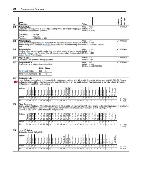
3-90 Programming and ParametersNameNo. Description813 Anlg In3 ValueDisplays the actual input value at Analog Input 3. Analog Input 3 is a uni-polar voltage inputonly and cannot be configured for current.ValuesUnits: VoltsDefault: 0.0Min/Max: 0.0/10.0LinkableRead-WriteData TypeRO RealType of Input = VoltagePolarity= Uni-PolarResolution = 10 bit (0 to +1023)814 Anlg In3 ScaleUnits: /1vScales the raw analog input data plus the input offset to the desired data range. The scaled Default: 0.0000data for Analog Input 3 is displayed in Par 812 [Anlg In3 Data] and is available for usage in the Min/Max: -/+2200000000.0000drive.815 Anlg In3 OffsetUnits: VoltsApplies an offset to Analog Input 3. Use the offset to correct for zero signal errors or to create Default: 0.0an offset to the actual input. The output of the A/D converter is summed with this parameter to Min/Max: -/+20.0produce Par 813 [Anlg In3 Value].816 AI 3 Filt GainProvides the Lead term for the Analog Input 3 filter.817 Anlg In3 Filt BWProvides the Lag term for the Analog Input 3 filter.Light HeavyPar 816 [Al 3 Filt Gain 0.25 0.1Par 817 [Anlg In3 Filt BW] 50 10Default: 1.0Min/Max: -/+5.0Units: R/SDefault: 0.0000Min/Max: 0.0000/3760.0000✓✓✓✓RW RealRW RealRW RealRW Real821 Analog I/O UnitsUse to configure the type of units for the analog I/O. For analog inputs, configure bits 0 & 1 to match the selection with hardware switch S5. Bit 2 [AI3 Thermstr]configures analog input 3 for a thermistor input with range of 0 to 3V. Bits 16 &17 are used to configure the analog outputs for current or voltage. No hardwareconfiguration is needed for the analog outputs.OptionsReservedReservedReservedReservedReservedReservedReservedReservedReservedReservedReservedReservedReservedReservedAO2 CurrentAO1 CurrentReservedReservedReservedReservedReservedReservedReservedReservedReservedReservedReservedReservedReservedAI3 ThermstrAI2 CurrentAI1 CurrentDefault 0 0 0 0 0 0 0 0 0 0 0 0 0 0 0 0 0 0 0 0 0 0 0 0 0 0 0 0 0 0 0 00 = FalseBit 31 30 29 28 27 26 25 24 23 22 21 20 19 18 17 16 15 14 13 12 11 10 9 8 7 6 5 4 3 2 1 0 1 = True823 DigIn DebounceSets the amount of de-bounce (filtering) for each digital input. This is used to remove unwanted on/off cycling (chatter) on the digital inputs caused by relay bounce.Each digital input de-bounce is configured separately from 0.5ms to 8.0ms. The bit selections are cumulative for each digital input (1 - 6).Example: bit 4 & 2 & 1 on = 5.5ms of de-bounce for digital input 1.OptionsReservedDI6 8.0msDI6 4.0msDI6 2.0msDI6 1.0msDI6 0.5msDI5 8.0msDI5 4.0msDI5 2.0msDI5 1.0msDI5 0.5msDI4 8.0msDI4 4.0msDI4 2.0msDI4 1.0msDI4 0.5msDI3 8.0msDI3 4.0msDI3 2.0msDI3 1.0msDI3 0.5msDI2 8.0msDI2 4.0msDI2 2.0msDI2 1.0msDI2 0.5msDI1 8.0msDI1 4.0msDI1 2.0msDI1 1.0msDI1 0.5msReservedDefault 0 0 0 0 0 0 0 0 0 0 0 0 1 0 1 0 0 0 0 0 0 0 0 1 0 0 0 0 0 0 1 0Bit 31 30 29 28 27 26 25 24 23 22 21 20 19 18 17 16 15 14 13 12 11 10 9 8 7 6 5 4 3 2 1 0 0 = False1 = True824 Local I/O StatusDisplays the status of the local I/O.OptionsReservedReservedReservedReservedReservedReservedReservedReservedReservedReservedReservedReservedReservedRelay Out 3DigOut 2DigOut 1SafeOffInputReservedReservedReservedReservedReservedReservedReservedReservedDigIn 6DigIn 5DigIn 4DigIn 3DigIn 2DigIn 1Hw Enbl BypsDefault 0 0 0 0 0 0 0 0 0 0 0 0 0 0 0 0 0 0 0 0 0 0 0 0 0 0 0 0 0 0 0 0Bit 31 30 29 28 27 26 25 24 23 22 21 20 19 18 17 16 15 14 13 12 11 10 9 8 7 6 5 4 3 2 1 00 = False1 = True