User Manual High Performance AC Drive
User Manual High Performance AC Drive
User Manual High Performance AC Drive
- No tags were found...

You also want an ePaper? Increase the reach of your titles
YUMPU automatically turns print PDFs into web optimized ePapers that Google loves.
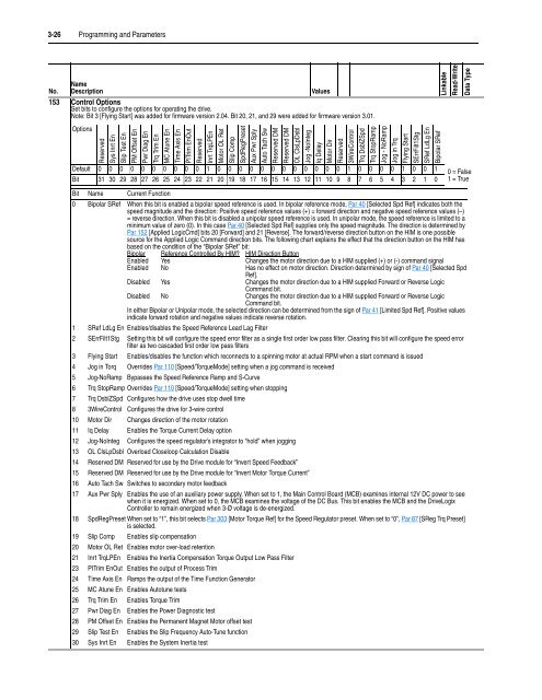
3-26 Programming and ParametersLinkableRead-WriteData TypeNo.NameDescriptionValues153 Control OptionsSet bits to configure the options for operating the drive.Note: Bit 3 [Flying Start] was added for firmware version 2.04. Bit 20, 21, and 29 were added for firmware version 3.01.OptionsReservedSys Inrt EnSlip Test EnPM Offset EnPwr Diag EnTrq Trim EnMC Atune EnTime Axis EnPITrim EnOutReservedInrt TrqLPEnMotor OL RetSlip CompSpdRegPresetAux Pwr SplyAuto Tach SwReserved DMReserved DMOL ClsLpDsblJog -NoIntegIq DelayMotor DirReserved3WireControlTrq DsblZSpdTrq StopRampJog - NoRampJog in TrqFlying StartSErrFilt1StgSRef LdLg EnBipolar SRefDefault 0 0 0 0 0 0 0 0 0 0 1 0 0 0 0 0 0 0 0 0 0 0 0 1 0 0 0 0 1 0 0 1Bit 31 30 29 28 27 26 25 24 23 22 21 20 19 18 17 16 15 14 13 12 11 10 9 8 7 6 5 4 3 2 1 00 = False1 = TrueBit Name Current Function0 Bipolar SRef When this bit is enabled a bipolar speed reference is used. In bipolar reference mode, Par 40 [Selected Spd Ref] indicates both thespeed magnitude and the direction: Positive speed reference values (+) = forward direction and negative speed reference values (–)= reverse direction. When this bit is disabled a unipolar speed reference is used. In unipolar mode, the speed reference is limited to aminimum value of zero (0). In this case Par 40 [Selected Spd Ref] supplies only the speed magnitude. The direction is determined byPar 152 [Applied LogicCmd] bits 20 [Forward] and 21 [Reverse]. The forward/reverse direction button on the HIM is one possiblesource for the Applied Logic Command direction bits. The following chart explains the effect that the direction button on the HIM hasbased on the condition of the “Bipolar SRef” bit:Bipolar Reference Controlled By HIM? HIM Direction ButtonEnabled Yes Changes the motor direction due to a HIM supplied (+) or (-) command signalEnabled No Has no effect on motor direction. Direction determined by sign of Par 40 [Selected SpdRef].Disabled Yes Changes the motor direction due to a HIM supplied Forward or Reverse LogicCommand bit.Disabled No Changes the motor direction due to a HIM supplied Forward or Reverse LogicCommand bit.In either Bipolar or Unipolar mode, the selected direction can be determined from the sign of Par 41 [Limited Spd Ref]. Positive valuesindicate forward rotation and negative values indicate reverse rotation.1 SRef LdLg En Enables/disables the Speed Reference Lead Lag Filter2 SErrFilt1Stg Setting this bit will configure the speed error filter as a single first order low pass filter. Clearing this bit will configure the speed errorfilter as two cascaded first order low pass filters3 Flying Start Enables/disables the function which reconnects to a spinning motor at actual RPM when a start command is issued4 Jog in Torq Overrides Par 110 [Speed/TorqueMode] setting when a jog command is received5 Jog-NoRamp Bypasses the Speed Reference Ramp and S-Curve6 Trq StopRamp Overrides Par 110 [Speed/TorqueMode] setting when stopping7 Trq DsblZSpd Configures how the drive uses stop dwell time8 3WireControl Configures the drive for 3-wire control10 Motor Dir Changes direction of the motor rotation11 Iq Delay Enables the Torque Current Delay option12 Jog-NoInteg Configures the speed regulator’s integrator to “hold” when jogging13 OL ClsLpDsbl Overload Closeloop Calculation Disable14 Reserved DM Reserved for use by the <strong>Drive</strong> module for “Invert Speed Feedback”15 Reserved DM Reserved for use by the <strong>Drive</strong> module for “Invert Motor Torque Current”16 Auto Tach Sw Switches to secondary motor feedback17 Aux Pwr Sply Enables the use of an auxiliary power supply. When set to 1, the Main Control Board (MCB) examines internal 12V DC power to seewhen it is energized. When set to 0, the MCB examines the voltage of the DC Bus. This bit enables the MCB and the <strong>Drive</strong>LogixController to remain energized when 3-Ø voltage is de-energized.18 SpdRegPreset When set to “1”, this bit selects Par 303 [Motor Torque Ref] for the Speed Regulator preset. When set to “0”, Par 87 [SReg Trq Preset]is selected.19 Slip Comp Enables slip compensation20 Motor OL Ret Enables motor over-load retention21 Inrt TrqLPEn Enables the Inertia Compensation Torque Output Low Pass Filter23 PITrim EnOut Enables the output of Process Trim24 Time Axis En Ramps the output of the Time Function Generator25 MC Atune En Enables Autotune tests26 Trq Trim En Enables Torque Trim27 Pwr Diag En Enables the Power Diagnostic test28 PM Offset En Enables the Permanent Magnet Motor offset test29 Slip Test En Enables the Slip Frequency Auto-Tune function30 Sys Inrt En Enables the System Inertia test