- Page 2 and 3:
Autodesk AutoCAD 2018 and Inventor
- Page 4:
For Technical Support, contact us a
- Page 7 and 8:
Chapter 3: Drawing Aids ...........
- Page 9 and 10:
Exercise 1 ........................
- Page 11 and 12:
Using the Fillet Edge tool ........
- Page 13 and 14:
Starting a New Assembly File ......
- Page 15 and 16:
TUTORIAL 7 ........................
- Page 17 and 18:
INTRODUCTION AutoCAD is the industr
- Page 21 and 22:
Part 1: AutoCAD Basics
- Page 23 and 24:
Part 1: AutoCAD Basics Starting Aut
- Page 25 and 26:
Part 1: AutoCAD Basics Tip: If the
- Page 27 and 28:
Part 1: AutoCAD Basics Graphics Win
- Page 29 and 30:
Part 1: AutoCAD Basics Infer Constr
- Page 31 and 32:
Part 1: AutoCAD Basics Dynamic Inpu
- Page 33 and 34:
Part 1: AutoCAD Basics Annotation S
- Page 35 and 36:
Part 1: AutoCAD Basics balloon noti
- Page 37 and 38:
Part 1: AutoCAD Basics Changing the
- Page 39 and 40:
Part 1: AutoCAD Basics Shortcut Men
- Page 41 and 42:
Part 1: AutoCAD Basics However, if
- Page 43 and 44:
Part 1: AutoCAD Basics The Select T
- Page 45 and 46:
Part 1: AutoCAD Basics Command List
- Page 47 and 48:
Part 1: AutoCAD Basics DIMSTYLE D U
- Page 49 and 50:
Part 1: AutoCAD Basics DIST DI Used
- Page 51 and 52:
Part 1: AutoCAD Basics INSERT I Use
- Page 53 and 54:
Part 1: AutoCAD Basics MSPACE MS Us
- Page 55 and 56:
Part 1: AutoCAD Basics QUICKCALC QC
- Page 57 and 58:
Part 1: AutoCAD Basics SPELL SP Use
- Page 59 and 60:
Part 1: AutoCAD Basics XLINE XL Use
- Page 61 and 62:
Part 1: AutoCAD Basics CONE Used to
- Page 63 and 64:
Part 1: AutoCAD Basics MATERIALASSI
- Page 65 and 66:
Part 1: AutoCAD Basics SPACETRANS U
- Page 67 and 68:
Part 1: AutoCAD Basics 46
- Page 69 and 70:
Part 1: AutoCAD Basics below. Turn
- Page 71 and 72:
Part 1: AutoCAD Basics Save the fi
- Page 73 and 74:
Part 1: AutoCAD Basics Example 2(Ce
- Page 75 and 76:
Part 1: AutoCAD Basics Select the
- Page 77 and 78:
Part 1: AutoCAD Basics Pick a poin
- Page 79 and 80:
Part 1: AutoCAD Basics Specify th
- Page 81 and 82:
Part 1: AutoCAD Basics methods are
- Page 83 and 84:
Part 1: AutoCAD Basics Activate th
- Page 85 and 86:
Part 1: AutoCAD Basics 64 Drawing B
- Page 87 and 88:
Part 1: AutoCAD Basics On the Stat
- Page 89 and 90:
Part 1: AutoCAD Basics easily turn-
- Page 91 and 92:
Part 1: AutoCAD Basics click the do
- Page 93 and 94:
Part 1: AutoCAD Basics From: Locate
- Page 95 and 96:
Part 1: AutoCAD Basics Using Object
- Page 97 and 98:
Part 1: AutoCAD Basics Click Zoo
- Page 99 and 100:
Part 1: AutoCAD Basics Using Zoom-S
- Page 101 and 102:
Part 1: AutoCAD Basics 80
- Page 103 and 104:
Part 1: AutoCAD Basics The Copy too
- Page 105 and 106:
Part 1: AutoCAD Basics command line
- Page 107 and 108:
Part 1: AutoCAD Basics Define secon
- Page 109 and 110:
Part 1: AutoCAD Basics The Stretch
- Page 111 and 112:
Part 1: AutoCAD Basics Rotate Items
- Page 113 and 114:
Part 1: AutoCAD Basics The Path Arr
- Page 115 and 116:
Part 1: AutoCAD Basics The followin
- Page 117 and 118:
Part 1: AutoCAD Basics Convert to A
- Page 119 and 120:
Part 1: AutoCAD Basics Refine Verti
- Page 121 and 122:
Part 1: AutoCAD Basics Type 80 in
- Page 123 and 124:
Part 1: AutoCAD Basics Click OK; t
- Page 125 and 126:
Part 1: AutoCAD Basics Type 5 and
- Page 127 and 128:
Part 1: AutoCAD Basics 106
- Page 129 and 130:
Part 1: AutoCAD Basics 108
- Page 131 and 132:
Part 1: AutoCAD Basics 110
- Page 133 and 134:
Part 1: AutoCAD Basics 112
- Page 135 and 136:
Part 1: AutoCAD Basics created by u
- Page 137 and 138:
Part 1: AutoCAD Basics Use the Off
- Page 139 and 140:
Part 1: AutoCAD Basics Click the C
- Page 141 and 142:
Part 1: AutoCAD Basics Move the p
- Page 143 and 144:
Part 1: AutoCAD Basics Select t
- Page 145 and 146:
Part 1: AutoCAD Basics Click the
- Page 147 and 148:
Part 1: AutoCAD Basics Exercise 4 C
- Page 149 and 150:
Part 1: AutoCAD Basics Crea
- Page 151 and 152:
Part 1: AutoCAD Basics Click Annot
- Page 153 and 154:
Part 1: AutoCAD Basics Diameter DIA
- Page 155 and 156:
Part 1: AutoCAD Basics Click Anno
- Page 157 and 158:
Part 1: AutoCAD Basics Break DIMBRE
- Page 159 and 160:
Part 1: AutoCAD Basics Click Zoom
- Page 161 and 162:
Part 1: AutoCAD Basics Select the
- Page 163 and 164:
Part 1: AutoCAD Basics On the Home
- Page 165 and 166:
Part 1: AutoCAD Basics Click OK
- Page 167 and 168:
Part 1: AutoCAD Basics Position Coc
- Page 169 and 170:
Part 1: AutoCAD Basics Click Home
- Page 171 and 172:
Part 1: AutoCAD Basics Press ENTER
- Page 173 and 174:
Part 1: AutoCAD Basics Right-click
- Page 175 and 176:
Part 1: AutoCAD Basics Editing Dime
- Page 177 and 178:
Part 1: AutoCAD Basics In the Prop
- Page 179 and 180:
Part 1: AutoCAD Basics Method: Limi
- Page 181 and 182:
Part 1: AutoCAD Basics Constraint F
- Page 183 and 184:
Part 1: AutoCAD Basics Select a po
- Page 185 and 186:
Part 1: AutoCAD Basics Click Par
- Page 187 and 188:
Part 1: AutoCAD Basics Click the A
- Page 189 and 190:
Part 1: AutoCAD Basics Also, you wi
- Page 191 and 192:
Part 1: AutoCAD Basics Click the P
- Page 193 and 194:
Part 1: AutoCAD Basics Exercise 2 I
- Page 195 and 196:
Part 1: AutoCAD Basics Example 2: I
- Page 197 and 198:
Part 1: AutoCAD Basics Click the P
- Page 199 and 200:
Part 1: AutoCAD Basics You can also
- Page 201 and 202:
Part 1: AutoCAD Basics Example: Cr
- Page 203 and 204:
Part 1: AutoCAD Basics Pick a poin
- Page 205 and 206:
Part 1: AutoCAD Basics 184
- Page 207 and 208:
Part 1: AutoCAD Basics Enter
- Page 209 and 210:
Part 1: AutoCAD Basics Set the Ann
- Page 211 and 212:
Part 1: AutoCAD Basics following ex
- Page 213 and 214:
Part 1: AutoCAD Basics In the Ins
- Page 215 and 216:
Part 1: AutoCAD Basics Using Tool P
- Page 217 and 218:
Part 1: AutoCAD Basics Enter 4 as
- Page 219 and 220:
Part 1: AutoCAD Basics Expand the
- Page 221 and 222:
Part 1: AutoCAD Basics option can b
- Page 223 and 224:
Part 1: AutoCAD Basics Example 1:
- Page 225 and 226:
Part 1: AutoCAD Basics Select the
- Page 227 and 228:
Part 1: AutoCAD Basics Select a p
- Page 229 and 230:
Part 1: AutoCAD Basics Double-cli
- Page 231 and 232:
Part 1: AutoCAD Basics 210
- Page 233 and 234:
Part 1: AutoCAD Basics Click the L
- Page 235 and 236: Part 1: AutoCAD Basics Use the Pa
- Page 237 and 238: Part 1: AutoCAD Basics Deactivate
- Page 239 and 240: Part 1: AutoCAD Basics Primary Unit
- Page 241 and 242: Part 1: AutoCAD Basics Object Scale
- Page 243 and 244: Part 1: AutoCAD Basics Set Paper T
- Page 245 and 246: Part 1: AutoCAD Basics 224
- Page 247 and 248: Part 1: AutoCAD Basics Select the
- Page 249 and 250: Part 1: AutoCAD Basics Toolbar; the
- Page 251 and 252: Part 1: AutoCAD Basics also downloa
- Page 253 and 254: Part 1: AutoCAD Basics On the ribb
- Page 255 and 256: Part 1: AutoCAD Basics 234
- Page 257 and 258: Part 1: AutoCAD Basics Tip: If the
- Page 259 and 260: Part 1: AutoCAD Basics rotate the m
- Page 261 and 262: Part 1: AutoCAD Basics Click Home
- Page 263 and 264: Part 1: AutoCAD Basics down > Wiref
- Page 265 and 266: Part 1: AutoCAD Basics become paral
- Page 267 and 268: Part 1: AutoCAD Basics Creating Oth
- Page 269 and 270: Part 1: AutoCAD Basics The other op
- Page 271 and 272: Part 1: AutoCAD Basics Click S
- Page 273 and 274: Part 1: AutoCAD Basics Change th
- Page 275 and 276: Part 1: AutoCAD Basics Make the Ske
- Page 277 and 278: Part 1: AutoCAD Basics Activat
- Page 279 and 280: Part 1: AutoCAD Basics Select the
- Page 281 and 282: Part 1: AutoCAD Basics Using the He
- Page 283 and 284: Part 1: AutoCAD Basics 262
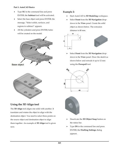
- Page 285: Part 1: AutoCAD Basics be moved as
- Page 289 and 290: Part 1: AutoCAD Basics three points
- Page 291 and 292: Part 1: AutoCAD Basics Press ENTER
- Page 293 and 294: Part 1: AutoCAD Basics Using the Of
- Page 295 and 296: Part 1: AutoCAD Basics Select the c
- Page 297 and 298: Part 1: AutoCAD Basics Press ENTER
- Page 299 and 300: Part 1: AutoCAD Basics Set the Sca
- Page 301 and 302: Part 1: AutoCAD Basics Select the
- Page 303 and 304: Part 1: AutoCAD Basics 282
- Page 305 and 306: Part 1: AutoCAD Basics 284
- Page 307 and 308: Part 1: AutoCAD Basics Click to c
- Page 309 and 310: Part 1: AutoCAD Basics 118, and the
- Page 311 and 312: Part 1: AutoCAD Basics Deactivat
- Page 313 and 314: Part 1: AutoCAD Basics Press Esc t
- Page 315 and 316: Part 1: AutoCAD Basics base point.
- Page 317 and 318: Part 1: AutoCAD Basics Move the po
- Page 319 and 320: Part 1: AutoCAD Basics Trim the un
- Page 321 and 322: Part 1: AutoCAD Basics Likewise, c
- Page 323 and 324: Part 1: AutoCAD Basics Offset the
- Page 325 and 326: Part 1: AutoCAD Basics Select the
- Page 327 and 328: Part 1: AutoCAD Basics Arranging Ob
- Page 329 and 330: Part 1: AutoCAD Basics Creating Gri
- Page 331 and 332: Part 1: AutoCAD Basics Insert the
- Page 333 and 334: Part 1: AutoCAD Basics Save and cl
- Page 335 and 336: Part 2: Inventor Basics
- Page 337 and 338:
Part 2: Autodesk Inventor Basics In
- Page 339 and 340:
Part 2: Autodesk Inventor Basics Th
- Page 341 and 342:
Part 2: Autodesk Inventor Basics Qu
- Page 343 and 344:
Part 2: Autodesk Inventor Basics Di
- Page 345 and 346:
Part 2: Autodesk Inventor Basics To
- Page 347 and 348:
Part 2: Autodesk Inventor Basics 32
- Page 349 and 350:
Part 2: Autodesk Inventor Basics 9.
- Page 351 and 352:
Part 2: Autodesk Inventor Basics No
- Page 353 and 354:
Part 2: Autodesk Inventor Basics Te
- Page 355 and 356:
Part 2: Autodesk Inventor Basics Ad
- Page 357 and 358:
Part 2: Autodesk Inventor Basics St
- Page 359 and 360:
Part 2: Autodesk Inventor Basics Th
- Page 361 and 362:
Part 2: Autodesk Inventor Basics A
- Page 363 and 364:
Part 2: Autodesk Inventor Basics 2.
- Page 365 and 366:
Part 2: Autodesk Inventor Basics 6.
- Page 367 and 368:
Part 2: Autodesk Inventor Basics Th
- Page 369 and 370:
Part 2: Autodesk Inventor Basics An
- Page 371 and 372:
Part 2: Autodesk Inventor Basics 3.
- Page 373 and 374:
Part 2: Autodesk Inventor Basics 13
- Page 375 and 376:
Part 2: Autodesk Inventor Basics 2.
- Page 377 and 378:
Part 2: Autodesk Inventor Basics Pl
- Page 379 and 380:
Part 2: Autodesk Inventor Basics 9.
- Page 381 and 382:
Part 2: Autodesk Inventor Basics 26
- Page 383 and 384:
Part 2: Autodesk Inventor Basics 36
- Page 385 and 386:
Part 2: Autodesk Inventor Basics Ed
- Page 387 and 388:
Part 2: Autodesk Inventor Basics 4.
- Page 389 and 390:
Part 2: Autodesk Inventor Basics Cr
- Page 391 and 392:
Part 2: Autodesk Inventor Basics Ad
- Page 393 and 394:
Part 2: Autodesk Inventor Basics 12
- Page 395 and 396:
Part 2: Autodesk Inventor Basics 3.
- Page 397 and 398:
Part 2: Autodesk Inventor Basics 4.
- Page 399 and 400:
Part 2: Autodesk Inventor Basics 7.
- Page 401 and 402:
Part 2: Autodesk Inventor Basics 16
- Page 403 and 404:
Part 2: Autodesk Inventor Basics 30
- Page 405 and 406:
Part 2: Autodesk Inventor Basics 4.
- Page 407 and 408:
Part 2: Autodesk Inventor Basics 6.
- Page 409 and 410:
Part 2: Autodesk Inventor Basics 5.
- Page 411 and 412:
Part 2: Autodesk Inventor Basics 2.
- Page 413 and 414:
Part 2: Autodesk Inventor Basics 19
- Page 415 and 416:
Part 2: Autodesk Inventor Basics 2.
- Page 417 and 418:
Part 2: Autodesk Inventor Basics 34
- Page 419 and 420:
Part 2: Autodesk Inventor Basics 3.
- Page 421 and 422:
Part 2: Autodesk Inventor Basics 8.
- Page 423 and 424:
Part 2: Autodesk Inventor Basics 2.
- Page 425 and 426:
Part 2: Autodesk Inventor Basics 29
- Page 427 and 428:
Part 2: Autodesk Inventor Basics 2D
- Page 429 and 430:
Part 2: Autodesk Inventor Basics 21
- Page 431 and 432:
Part 2: Autodesk Inventor Basics 35
- Page 433 and 434:
Part 2: Autodesk Inventor Basics Cr
- Page 435 and 436:
Part 2: Autodesk Inventor Basics 14
- Page 437 and 438:
Part 2: Autodesk Inventor Basics Le
- Page 439 and 440:
Part 2: Autodesk Inventor Basics Ad
- Page 441 and 442:
Part 2: Autodesk Inventor Basics va
- Page 443 and 444:
Part 2: Autodesk Inventor Basics Cr
- Page 445 and 446:
Part 2: Autodesk Inventor Basics 6.
- Page 447 and 448:
Part 2: Autodesk Inventor Basics 6.
- Page 449 and 450:
Part 2: Autodesk Inventor Basics 4.
- Page 451 and 452:
Part 2: Autodesk Inventor Basics 2.
- Page 453 and 454:
Part 2: Autodesk Inventor Basics 6.
- Page 455 and 456:
Part 2: Autodesk Inventor Basics 8.
- Page 457 and 458:
Part 2: Autodesk Inventor Basics Ch
- Page 459 and 460:
Part 2: Autodesk Inventor Basics 3.
- Page 461 and 462:
Part 2: Autodesk Inventor Basics Cr
- Page 463 and 464:
Part 2: Autodesk Inventor Basics
- Page 465 and 466:
Part 2: Autodesk Inventor Basics 8.
- Page 467 and 468:
Part 2: Autodesk Inventor Basics 14
- Page 469 and 470:
Part 2: Autodesk Inventor Basics Cr
- Page 471 and 472:
Part 2: Autodesk Inventor Basics Yo
- Page 473 and 474:
Part 2: Autodesk Inventor Basics 12
- Page 475 and 476:
Part 2: Autodesk Inventor Basics Ch
- Page 477 and 478:
Part 2: Autodesk Inventor Basics 38
- Page 479 and 480:
Part 2: Autodesk Inventor Basics 10
- Page 481 and 482:
Part 2: Autodesk Inventor Basics 8.
- Page 483 and 484:
Part 2: Autodesk Inventor Basics 6.
- Page 485 and 486:
Part 2: Autodesk Inventor Basics 4.
- Page 487 and 488:
Part 2: Autodesk Inventor Basics Th
- Page 489 and 490:
Part 2: Autodesk Inventor Basics 7.
- Page 491 and 492:
Part 2: Autodesk Inventor Basics 3.
- Page 493 and 494:
Part 2: Autodesk Inventor Basics Dr
- Page 495 and 496:
Part 2: Autodesk Inventor Basics On
- Page 497 and 498:
Part 2: Autodesk Inventor Basics 1.
- Page 499 and 500:
Part 2: Autodesk Inventor Basics 2.
- Page 501 and 502:
Part 2: Autodesk Inventor Basics 11
- Page 503 and 504:
Part 2: Autodesk Inventor Basics 32
- Page 505 and 506:
Part 2: Autodesk Inventor Basics 6.
- Page 507 and 508:
Part 2: Autodesk Inventor Basics 48
- Page 509 and 510:
Part 2: Autodesk Inventor Basics Pr
- Page 511 and 512:
Part 2: Autodesk Inventor Basics 20
- Page 513 and 514:
Part 2: Autodesk Inventor Basics 22